Thursday, January 20, 2022

Huawei ONT - Mesh Network

We know that Wi-Fi networks have become a necessity for home networking users, and while home broadband services at 100 Mbit/s and up to 1000 Mbit/s are rapidly becoming popularized, it has emerged the need for greater Wi-Fi coverage within a home. Users want access to Wi-FI network in all the amenities of their residence and have a great experience.


To achieve these goals, Huawei has a Mesh solution using the following equipments:


GPON ONT/ONU Gateway EG8145V5 e EG8245W5-6T:
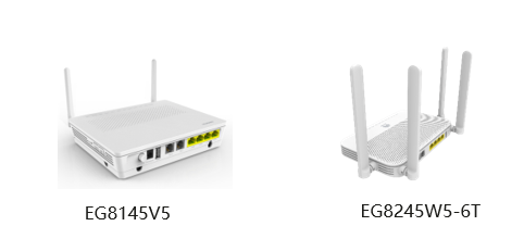

ONTS


ONT Edge WA8021V5


ONT EDGE


Characteristics of a Mesh Network:


Mesh networking supports flexible Wi-Fi expansion


Supports mesh networking (tree) and two-level cascading distributed networking
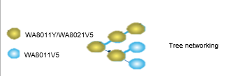

tree


Smart Wi-Fi seamless roaming


Supports 802.11k/v and roaming switching within 200 ms
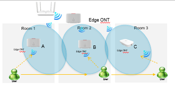

Smart Roaming


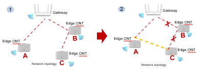
Quick self-healing and service recovery within 30s

smart


  • Connection along the red dotted lines ensures normal service.

  • When a networking fault occurs, a connection along the yellow dotted lines is established.


How to set up a Mesh network:


*Applicable to connection with Huawei gateways with the latest software version


    1. Configure the  Wi-FI on ONT Home Gateway


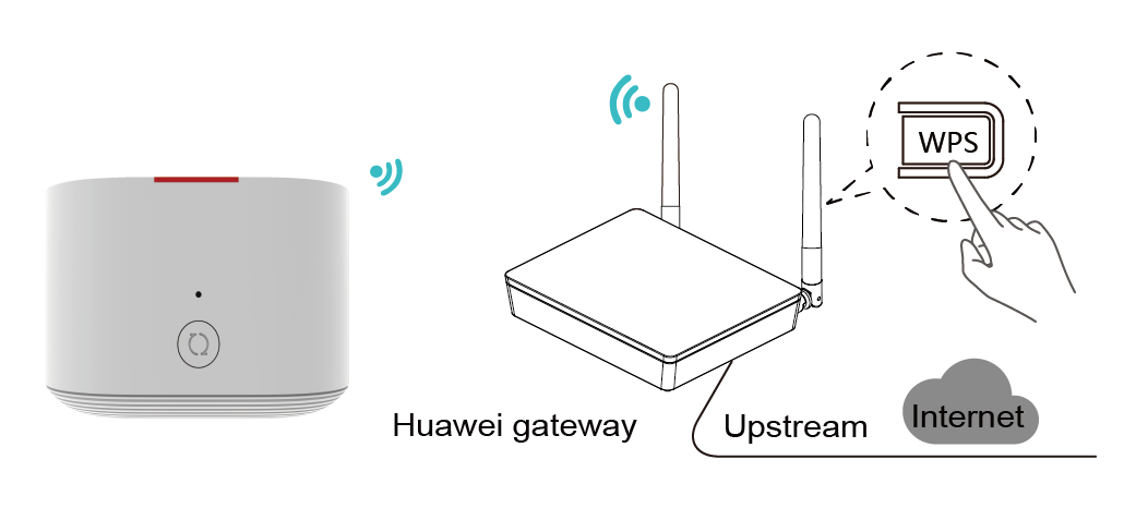
    2. Place the edge ONT near a Huawei gateway (within 2 m) and connect the power cable of edge ONT to a socket.


    3. After the edge ONT is powered on, the Huawei gateway can discover edge ONT, and the WPS indicator of the gateway blinks slowly.


    4. Press the WPS button of the gateway once. The WPS indicator and edge ONT indicator change to blink quickly.

Huawei

    5Move the edge ONT to the position where the Wi-Fi coverage is to be expanded. After the indicator is steady white, the edge ONT can access the Internet. No further operation is required.


edge ONT


The Wi-Fi name and password of the edge ONT are automatically synchronized from the Wi-Fi of the Huawei gateway.


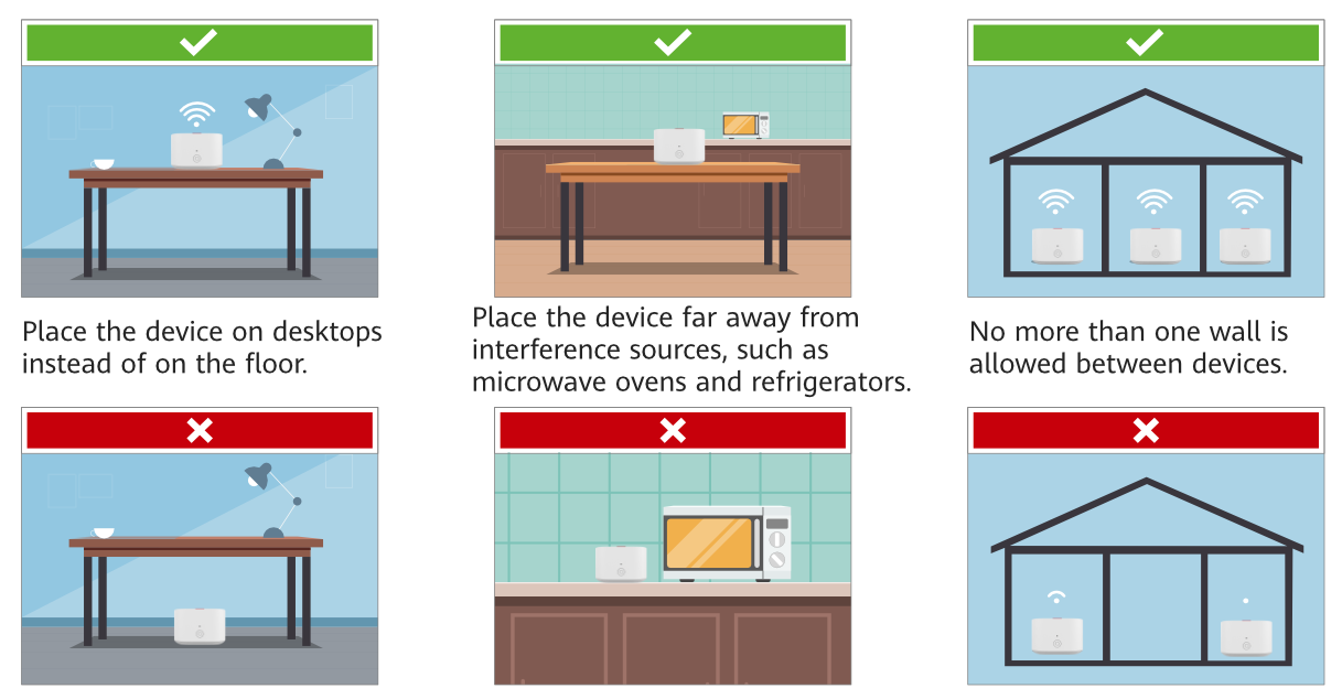
Recommendations for installation Edge ONT:


✔ There are no more than two walls between edge ONTs and the Huawei gateway.


✔ Edge ONTs and the Huawei gateway are placed on the same floor.


  • When the WA8021V5 is connected to a home gateway over the 5 GHz frequency band:


  •  If the signal strength at the WA8021V5 is greater than –65 dBm, the WA8021V5 is placed in a proper position.


  • If the signal strength at the WA8021V5 is less than -73 dBm, you are advised to relocate the WA8021V5 to ensure that the signal strength is greater than -73 dBm.


  • When the WA8021V5 is connected to a home gateway over the 2.4 GHz frequency band:


  • If the signal strength at the WA8021V5 is greater than –65 dBm, the WA8021V5 is placed in a proper position.


  • If the signal strength at the WA8021V5 is less than –65 dBm, you are advised to relocate the WA8021V5 to ensure that the signal strength is greater than –65 dBm.

place

Tuesday, December 14, 2021

What Is Liquid OTN?

Traditional OTN technologies are mainly used on backbone and metro networks to carry services at a rate higher than 1 Gbit/s. After OTN devices are deployed on metro or access networks, the following challenges emerge: inelastic pipes (ODU0 at minimum), small number of connections, and inflexible bandwidth adjustment.

With the optical service unit flexible container (OSUflex), Liquid OTN optimizes the multiplexing and mapping paths, so that the OSUflex can be directly mapped to the higher-order pipes to satisfy different service bandwidth requirements.

  • OSUflex over ODUflex: coexistence and interworking with existing OTN or DWDM networks
  • OSUflex over ODUCn: new Liquid OTN networks


With the Liquid OTN technology, an OPUk payload in an existing OTN system is divided into physically isolated communication pipes with a fixed frame length. The OPUk/flex payload area is divided into multiple payload blocks (PBs). The following figure uses OPU4 as an example.

  • When multiple channels of OSUflex signals are mapped and multiplexed into OPUk/flex payloads, a 12-bit tributary port number (TPN) needs to be added based on each channel of OSUflex signals to identify the mapping between each channel of OSUflex signals and tributaries.
  • A TPN must be unique at the server layer to ensure that the receive end can correctly distinguish tributary port numbers. The TPN function is similar to the MSI function of OTN, and is a preferred manner. To be specific, a TPN is added based on the OSUflex frame to exactly form a PB.

Comparison Between MS-OTN and Liquid OTN


Summary

Liquid OTN has the following key capabilities:
  • Ubiquitous all-optical connectivity: Liquid OTN introduces OSUflex containers to support flexible bandwidth definition. Furthermore, network hard slices can achieve a fine granularity of 2 Mbit/s, bringing 500 times more connections.
  • Hitless bandwidth adjustment: Supports hitless bandwidth adjustment from 2 Mbit/s to 100 Gbit/s, ensuring zero service interruption and full use of network resources. e connections.
  • Ultra-low transmission latency: Significantly reduces the network transmission layers, provides differentiated latency levels, and reduces per-site latency by 70% to reach the microsecond level, adapting to different latency-sensitive scenarios.


Thursday, December 9, 2021

Ethernet switching - The working mechanism of a layer 3 switch

In the current live network environment, we can always see that it is the core switch like Huawei CE6800 switch that processing the data forwarding. You might be curious about that, isn't the switch forwarding Layer 2 data packets? Why are switches used at the core layer to forward data packets? Can the switch also handle IP packets? In this chapter, we will give you a detailed introduction to the working mechanism of the three-layer exchange.

As mentioned above, switches can be divided into layer 2 switches such as Huawei S1700 S2700 series and layer 3 switches, and Layer 3 switches can also forward IP packets based on the routing table, the same as routers. Is the working mechanism the same as that of routers? Obviously, the answer is no. Before comparing the forwarding process of the two in detail, let's briefly introduce the forwarding process of the three-layer switch, so that everyone can understand the forwarding process of the data packet in the layer 3 switches in more detail. For the forwarding of Layer 2 packets in the same network segment, the processing mechanism of the Layer 3 switch is the same as that of the Layer 2 switch, which is based on the destination MAC address. We will skip that part in this chapter. We are mainly concerned about the layer 3 IP packet forwarding across the network segment.

Brief architecture of the layer 3 switch

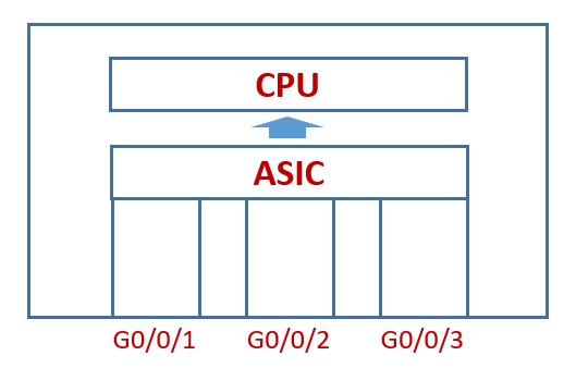
Figure 1: Brief architecture of the layer 3 switch

ASIC: Charge in layer 2 and layer 3 forwarding functions, including the MAC address table for layer 3 forwarding and the layer 3 forwarding table for IP forwarding;

CPU: Used for forwarding control. It mainly maintains software entries (including software routing tables, software ARP tables, etc.), and configures the ASIC's hardware layer 3 forwarding table according to the forwarding information of the software entries. Of course, the CPU itself can also complete the software three-layer forwarding.

Brief architecture of the layer 3 switch

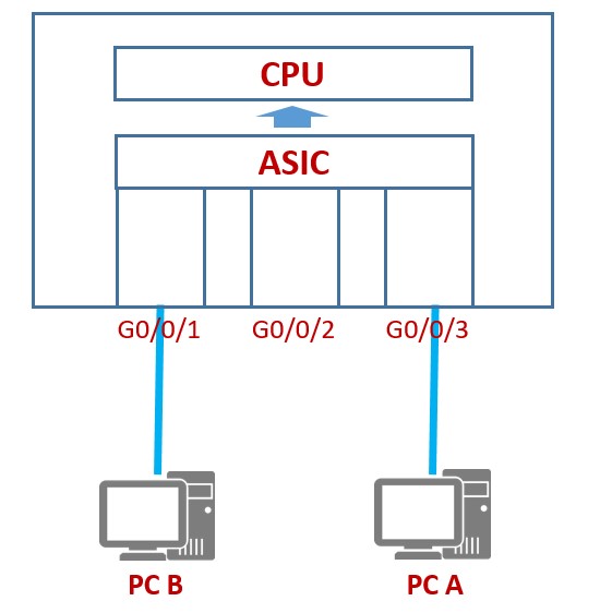
Figure 2PC A and PC B communicate across network segments

Assuming that PC A wants to communicate with PC B that is not on the same network segment, we will introduce the entire communication process in detail as follows:

  1. PC A realizes that PC B is not in the same network segment as itself, and it will send an ARP request message to request the MAC address of the gateway, that is, the MAC address of the switch.

  2. After receiving the ARP request, the switch responds with an ARP reply message to PC A. At the same time, it will also record the MAC address and IP address of PC A in the ARP table.

  3. PC A encapsulates the data packet (source IP: PC A, destination IP: PCB, source MAC: PC A, destination MAC: switch) and sends it to the switch.

  4. After the switch receives the modified message, it looks up the source MAC of the message and the VLAN where the port is located to update the MAC address table and then looks up the MAC table according to the destination MAC and VLAN number for forwarding (this is a layer 2 forwarding mechanism). But the switch discovers that the destination MAC is the MAC table of its own Layer 3 interface, and the switch realizes that this packet is either sent to itself or needs to be forwarded at Layer 3. Therefore, the switch searches for the three-layer table entry of the switching chip according to the destination IP. Since notable entry has been created before, the search fails. Then, the switch sends the message to the CPU for processing.

  5. The CPU searches the routing table according to the destination IP of the message, finds the matching item (if there is no match, the message will be discarded), and continues to look up the software ARP table, but the corresponding entry is not found.

  6. The switch sends ARP request packets on all interfaces of the VLAN corresponding to the destination IP, requesting the MAC address of the destination IP.

  7. PC B responds to the ARP reply message after receiving the request. After the switch learns the MAC, it will also record the corresponding data and send the message from PC A to PC B to complete the transfer from PC A to PC B. Communication.

From PC B to PC A, since the forwarding entry has been established on the switch, subsequent messages will not be sent to the CPU, and the table lookup and forwarding process will be completed directly on the forwarding chip.

It can be known from the above process that ASIC plays an extremely important role in the forwarding process of the layer 3 switches. It can realize fast forwarding after establishing the layer 3 forwarding entry after the first communication process, thereby eliminating the need for continuous lookup of the routing table. The mechanism not only speeds up the forwarding process but also saves the occupation of system CPU resources. This is also a huge difference compared to router layer three forwardings.

Back to the question at the beginning of this chapter, why the core device of the network is often the core switch because the destination IP address of the devices in the same network to exchange data with each other is very limited, when the establishment of the layer 3 forwarding table is completed, the core switch Data will be forwarded very efficiently. For data accessing the Internet, routers will have better processing capabilities than Layer 3 switches due to the vastly different destination addresses.

Thursday, November 25, 2021

XG (S) – PON | Motivation and Evolution

With the emergence of new applications and services that require more bandwidth, there is a need for the passive network to be able to support these services and deliver the necessary bandwidth. GPON passive networks have become a bottleneck for these services. Given the facts, we will have the rise of the next generation of GPON technology, XG(S)-PON (10G GPON).


Services


What’s XG (S) – PON?


XG (S) – PON is an enhanced next-generation PON technology that evolves from existing GPON technology standards. Some of the main features of this technology:


  • Higher bandwidth, capable of providing Internet access speeds of up to 10 Gbit/s. 4 times more than its predecessor GPON technology

  • Longest logical distance ≥ 60 km

  • Line Encryption on direction Downstream/Upstream

  • Split rate of up to 1:256


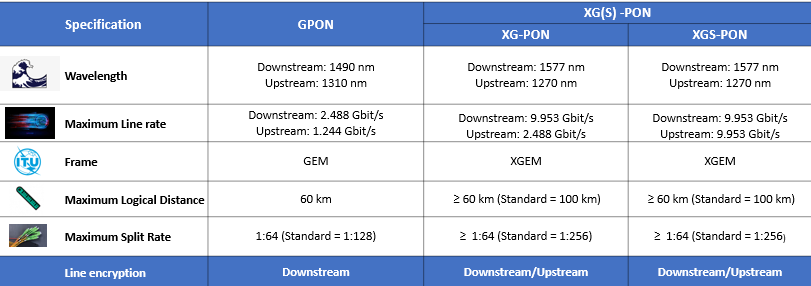
Differences between GPON, XG-PON and XGS-PON


difference


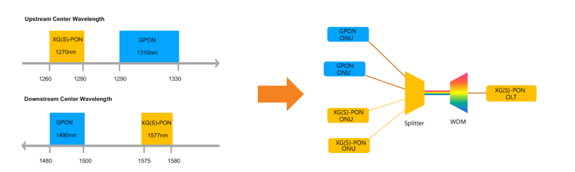
Evolution from GPON to XG(S)- PON


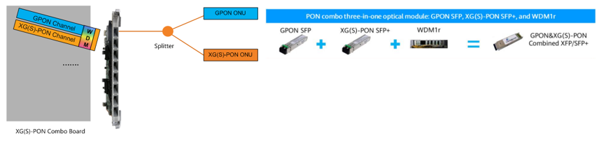
The wavelength of XG(S)-PON and GPON do not overlap. Therefore, they can share the same ODN network through Wavelength Division Multiplexing (WDM).


image


If the OLT does not support XG(S)-PON, you will need to add a new OLT that does. This is a disadvantage, as it will have additional cost when purchasing a new OLT, and you will have to discard the GPON OLT when your network is fully XG(S)-PON. A second disadvantage is the cost of purchasing a WDM1r multiplexer, and the space it will take up on your DC. Huawei has a great migration solution using XG(S) – PON Combo


What’s XG (S) – PON Combo?


On the same PON port, we can have two passive technologies, being GPON + XGPON or GPON + XGS-PON. In addition, we have an optical module combo that integrates the GPON optical module, XG(S)-PON optical module, and WDM multiplexer to share ODN resources without adding an external WDM multiplexer.


optical


Evolution Process


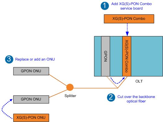
1. Add a board XG (S) – PON Combo

2. Migrate optical fiber from GPON port to XG port (S) – PON Combo

3. Add an ONU/ONT XG (S) – PON or change an existing ONU/ONT GPON


evo


Huawei Equipaments that support XG (S)


OLT

SmartAX MA5800 Series (X2, X7, X15, X17)

EA5801

Board

H902CSHD -  8-port XGS-PON and GPON Combo OLT interface board.

H902CSHF - 16-port XGS-PON and GPON Combo OLT interface board. It works together with the optical network unit (ONU) to provide XGS-PON and GPON access services.

H902CGHD - 8-port XG-PON and GPON Combo OLT interface board. It works together with the optical network unit (ONU) to provide XG-PON and GPON access services.

H901CGHF -16-port XG-PON and GPON Combo OLT interface board. It works together with the optical network unit (ONU) to provide XG-PON and GPON access services.


ONT

HN8546Q, XG-PON ONT, 4GE+1POTS+2USB+2.4G&5G

HN8145V, XG-PON ONT, 4*GE+1*POTS+1*USB+2.4G/5G WIFI

HN8346V, XG-PON ONT, 4GE+1POT+2USB+2.4G/5G Wi-Fi 

HN8546X6, XG-PON ONT, 4GE+2USB+1POT, 2.4G&5G Wi-Fi 6


Saturday, November 6, 2021

What is the application of Huawei 10*10G tributary board TTX?

As a type of 10*10G port OTN tributary board, Huawei TTX board converts between ten channels of 10GE LAN/10GE WAN/STM-64/OC-192/OTU2/OTU2e/FC800/FC1200 optical signals and ten channels of ODU2/ODU2e/ODUflex electrical signals through cross-connection.


For the position of the TTX board in the WDM system.


NOTE:
  • Only the TN55TTX supports FC800, FC1200, OTU2 and OTU2e services.
  • The cross-connection of ODUflex signals is supported only by the TN55TTX board.
Table 1 Client-side service mapping path supported by the board
BoardClient-Side ServiceBackplane-Side Service
TN54TTX10GE WAN/STM-64/OC-192ODU2
10GE LANODU2e
TN55TTX10GE WAN/STM-64/OC-192/OTU2ODU2
OTU2e/FC1200ODU2e
10GE LANODU2/ODU2e
FC800ODU2/ODUflex

Tuesday, September 28, 2021

How to test 1+1 Protection of the Cross-Connect Board and Clock Board for OptiX OSN 8800?

1+1 protection is configured by using the cross-connect board and clock board. This section describes how to test the 1+1 protection switching of the cross-connect board and clock board, thus ensuring that the protection switching is normal.

Prerequisites

For the OptiX OSN 8800 T16, slots 9 and 10 must house the high cross-connection, system control and clock processing board.

For the OptiX OSN 8800 T32, slots 9 and 10 must house the cross-connect board.

For the OptiX OSN 8800 T64, slots 9 and 43 (or slots 10 and 44) must house the cross-connect board.

For the OptiX OSN 8800 T32, slots 42 and 44 must house the clock board.

For the OptiX OSN 8800 T64, slots 75 and 86 must house the clock board.

The NE commissioning data must be configured.

Tools, Equipment, and Materials

NMS

Procedure

  1. Double click the ONE icon on the Physical Map, and the NE Panel tab is displayed.
  2. Right-click the NE icon and choose NE Explorer.
  3. Choose Configuration > Board 1+1 Configuration. Click Query. The queried Active Board should be the same as the Working Board.


    For the OptiX OSN 8800 T16, Working Board is the cross-connection, system control and clock processing board in slot 9, and Protection Board is the cross-connection, system control and clock processing board in slot 10. Active Board is the cross-connection, system control and clock processing board that is actually working.

    For the OptiX OSN 8800 T32, Working Board is the cross-connect board in slot 9, and Protection Board is the cross-connect board in slot 10.Active Board is the cross-connect board that is actually working.

    For the OptiX OSN 8800 T64, Working Board is the cross-connect board in slot 9 or 10, and Protection Board is the cross-connect board in slot 43 or 44. Active Board is the cross-connect board that is actually working.

    For the OptiX OSN 8800 T32, Working Board is the clock board in slot 42, and Protection Board is the clock board in slot 44. Active Board is the clock board that is actually working.

    For OptiX OSN 8800 T64, Working Board is the clock board in slot 75, and Protection Board is the clock board in slot 86. Active Board is the clock board that is actually working.

  4. Select Cross-Connect Board 1+1 Protection or Clock 1+1 Protection, and then click Working/Protection Switching. In the Microsoft Internet Explorer dialog box that is displayed, click OK. In the Operation Result dialog box that is displayed, click Close.

    When you select the cross-connect board or the clock board for switching, the cross-connect board and the clock board perform switching at the same time.

  5. Repeat step 3 to perform the query. The queried Active Board should be the same as the Protection Board.
  6. Select Cross-Connect Board 1+1 Protection or Clock 1+1 Protection, and then click Restore Working/Protection. In the Confirm dialog box that is displayed, click OK. In the Operation Result dialog box that is displayed, click Close.

    When you select the cross-connect board or the clock board for switching, the cross-connect board and the clock board perform switching at the same time.

    The 1+1 protection switching on the cross-connect boards and clock boards is non-revertive. When Protection Board becomes Active Board, restore the cross-connect boards and clock boards to the original working/protection state by removing the protection board, or by clicking Restore Working/Protection on the NMS.

  7. Repeat step 3 to perform the query. The queried Active Board should be the same as Working Board.

Friday, September 10, 2021

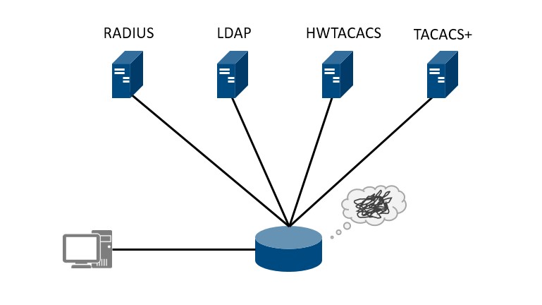
RADIUS, LDAP, HWTACACS, TACACS+ which one do I choose?

As one of the most important parts of the authentication network, the authentication server is responsible for the users' login information, usually the combination of username and password, verification. It can be said the authentication server is the most important barrier to keep illegal users from accessing. In this article, the most widely used authentication server, including RADIUS, LDAP, HWTACACS, and TACACS+, will be discussed.

authentication protocol

Figure 1: Authentication protocol selection

RADIUS

The RADIUS is a standard protocol that uses UDP 1812 for authentication and authorization, and UDP 1813 for accounting. As the most used authentication protocol, the most advantage of RADIUS is its standardization. RADIUS is normalization in RFC 2865, as the OSPF does, the RFC document restricts the vendors to use the unified communication mechanism for the protocol programming so that the RADIUS can be used between various vendors' devices. In other words, users are able to make a choice between different vendors, rather than binding with the specific vendor.

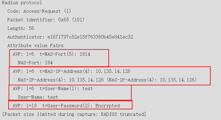
RADIUS uses the TLV packet structure to carry the information. For example, RADIUS uses the attribute User-Name, which length ranges from 1 byte to 253 bytes, to deliver the login user's account. Due to this TLV packet structure, RADIUS provides a flexible packet encapsulation, that allows the vendors to extend the protocol themselves. For example, Huawei extends the standard RADIUS attributes Vendor-Specific to deliver more private information, such as HW-Policy-Route, it specifies the next-hop address in the policy-based routing.

radius protocol

Figure 2 The RADIUS attributes

As we introduced, RADIUS uses the UDP 1812 for the authentication and authorization, in other words, RADIUS is not able to implement the authorization and authentication in different servers, this is totally different from the HWTACACS or TACACS+.

Despite the RADIUS advantages, the most disadvantage of RADIUS is the password field encryption only in the packets, which would lead to the user's information leakage.

LDAP

Before discussing the LDAP authentication, we'll introduce the LDAP firstly.

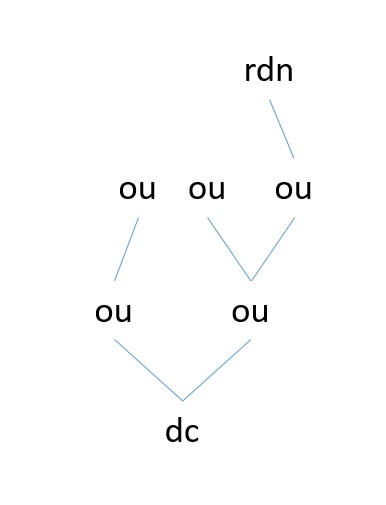
LDAP, short for Lightweight Directory Access Protocol, is an open, standard, and platform-crossing application protocol that is used for the distributed directory information service maintenance. It is transmitted through the HTTPS. The LDAP server which stores the data is quite different from the traditional database, unlike a table, the LDAP server stores the data in a tree structure, which is similar to the MIB and OID. Simply, the DN, distinguished name, marks the entrance of the query operation. When the DN is specified, the LDAP server will search the LDAP database according to the OU, organization unit, to get the wanted data.

LDAP

Figure 3: LDAP directory tree structure

In this kind of store, the data querying could be much faster than the other database. On the contrary, the data insertion is not the advantage of the LDAP server, actually, the data insertion is not a key index that the authentication service requires.

The same as the RADIUS, LDAP is also a standard protocol. On the other hand, since the LDAP is based on HTTPS, that means the transferring data could be encrypted and this makes the LDAP much safer than the RADIUS does.

When using the LDAP server for the authentication, the network device delivers the username and password to the LDAP server, and the server will search the LDAP directory tree for verification.

HWTACACS

HWTACACS is a private authentication protocol released by Huawei, Unlike the RADIUS, HWTACACS separates the authentication and authorization, which means authentication, authorization, and accounting can be implemented on different servers. But the private protocol limits the other vendors and manufacturers from using this protocol. On the other hand, HWTACACS supports the command recording to record the executed commands on the HWTACACS server for the accounting.

TACACS+

As one of the most important vendors, Cisco optimizes its TACACS and published the TACACS+. The TACACS+ is a private authentication protocol, which uses TCP 49 for transmission. And the most important disadvantage of this protocol is the protocol privateness, which means it can not be used by other vendors and manufacturers. The same as the HWTACACS, TACACS+ also provides independent authentication, authorization, and accounting.


If you have other questions about Huawei or Cisco switch, you can contact our supports@thunder-link.com.


More related:

LST7X48SX6S0


S12700E-4
S5721-28X-SI-24S-AC