Thursday, December 29, 2022

OLT enable MAC Address Anti-Floating Cause BRASs become Double VRRP Master

Problem Description

When two BRASs are connected through one OLT, occur VRRP became two masters.


Handling Process

1. Two BRASs are in the master state. This is because the VRRP packets sent from the active BRAS to the standby BRAS are discarded on the OLT side. The standby BRAS consider that the active BRAS is faulty and then becomes the active BRAS. Perform ACL statistics on the OLT. It is found that the port connected to the active BRAS receives VRRP packets.


1


Perform mirror on the OLT Huawei MA5680T for example port connecting the standby BRAS. It is found that VRRP packets are not sent out. Therefore, packets are lost on the OLT, as shown in the following figure.


1


2. The OLT discards VRRP packets sent from the active BRAS to the standby BRAS because anti-MAC address flapping is enabled. The port connected to the standby BRAS learns the virtual MAC address first, and then receiving a VRRP packet with the same virtual MAC address on master BRAS, master BRAS discards the packet due to a MAC address learning conflict.


Query the MAC address on the OLT. It is found that the virtual MAC address of the VRRP packet is learned on the port connected to the standby BRAS. The anti-MAC flapping function is enabled on the device. Therefore, the virtual MAC address of the VRRP packet is configured as a static MAC address to prevent flapping to other ports.


1


The virtual MAC address is learned on the port connected to the standby BRAS because the optical path between the active BRAS and the OLT is interrupted. As a result, services are switched to the standby BRAS, and the MAC address of the original port is deleted. The re-learning is performed on the port connected to the standby BRAS. After the optical path on the active BRAS recovers, the interface connected to the active BRAS receives a VRRP packet with the same virtual MAC address. In this case, the interface discards the VRRP packet because of a MAC address learning conflict.


Root Cause 

When two BRASs are connect through an OLT, they use the same virtual MAC address. The MAC address anti-flapping function is enabled on the OLT. After the port connected to the standby BRAS learns the virtual MAC address, the port connected to the active BRAS receives the VRRP packets with the same virtual MAC address. As a result, the port directly discards the VRRP packets due to MAC address learning conflicts. As a result, the standby BRAS fails to receive VRRP heart-beat packets from the active BRAS and becomes the active BRAS

Solution

Run the following command to disable the MAC address anti-flapping function on the OLT:

(config)#security anti-macduplicate disable

Tuesday, December 20, 2022

How to build a 10Gbps home network?

 In this day and age, the internet has become a necessity of life. In-home network design, we have various choices, Wi-Fi, wired, which one is more suitable for the home network? How should the home network be deployed? How to choose the network cable and ultimately how to build a 10Gbps home network?


Ethernet vs. Wi-Fi

Today's Wi-Fi bandwidth is getting bigger and bigger, with the latest commercial standard Wi-Fi 6 reaching 10Gbps wireless rates and the draft Wi-Fi 7 being revised to reach ultra-high speeds of 30Gbps. This leaves many wired out of reach. It seems that the future of Wi-Fi is bright. Although Wi-Fi speed is getting faster and faster, but wired networks also have unparalleled advantages:

  1. Stability: After the initial deployment of the network cable is completed, it will basically not be adjusted later and the transmission rate will remain basically the same.

  2. High speed: Although Wi-Fi 6 rate is high, but, at present, the network cable is basically 1Gbps rate or higher, the rate fully meets the home use.

  3. Extremely resistant to interference: the wired network rate will not be affected by microwave ovens, walls, etc.

  4. Wide range of use: Benefit from the RJ45 interface specification, all wired network interfaces (non-fiber) are consistent, even if the equipment replacement, will not affect its access to the existing network.

Therefore, when you have a lot of wired devices that need to access the network, the RJ45 network cable is your best choice, if you only have laptops and cell phones, only deploying Wi-Fi is also possible.

So how do we need to design and build the home network formation? What equipment do we need to use?


Modem

As the first device in the home, the optical GPON ONT modem is responsible for modulating the Ethernet digital signal from the intranet into a baseband signal or an optical signal. According to the type of modulated signal, it can be divided into electric modem and optical modem. With the popularity of optical fiber, more and more electrical modems are being replaced by optical cats.


home network design


On the optical modem device, there is usually one fiber optic interface and two to four Ethernet ports. The fiber optic interface is mainly used to connect to the fiber optic of the ISP, and the Ethernet port is mainly used to connect to the devices of the intranet. If the optical modem is only single-stored for signal modulation and demodulation, then usually it has only one Ethernet interface. If, in addition to signal modulation and demodulation, the optical modem is also responsible for other functions, such as a router, then it will have more Ethernet interfaces to meet the access of devices.

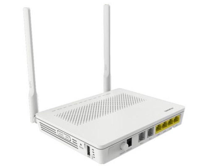
For example, Huawei HG8245H has an integrated optical modem, router, wireless router, and other functions.


Router

The router plays the role of connecting different networks and forwarding data. In home networks, it also plays the role of address translation.


Switch

Switches are not used much in home networks and are usually only used when there are many wired access devices. For example, in addition to wired PCs, there are NAS, servers, TVs, cameras, etc.
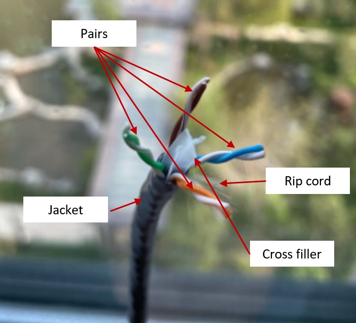

Network cable

Network cable as a cable to connect each wired device, while in the pre-decoration, once laid will not be changed. Therefore, it is especially important to determine the type of network cable and the design of the access point.

At present, the mainstream use is MODEM 6A UTP cable. Compared with MODEM 6A STP cable, UTP cable does not require grounding, the construction process requirements are simple.


home network design


CAT 6A vs CAT 7

I recommend CAT 6A over CAT 7 for the following reasons:

  1. CAT 6A UTP deployment is simpler.

    CAT 6A UTP and STP are two optional, in the home network of this short distance applications, the difference between the two is not much, but CAT 7 are with shielding layer, in terms of wire diameter, CAT 6A UTP general diameter is 6.2mm, CAT 7 line diameter reached 7.8mm, and with braided mesh shielding layer. CAT 7 line than CAT 6A UTP CAT 7 wire is much stiffer than CAT 6A UTP and will be more difficult to operate in the later threading.

  2. CAT 6A UTP crimp RJ45 connectors are simpler.

    In order to achieve high speed, CAT 7 adds a shielding layer between PVC jacket and cable pairs and requires grounding in the shielding layer, which puts higher requirements on the making of RJ45 connectors.

  3. CAT 6A is cheaper

    Compared to CAT 7 cable, CAT 6A is half the price per meter of CAT 7. The cost of use is much lower.


Home network build

A common home network networking structure is shown in the following figure.


home network design


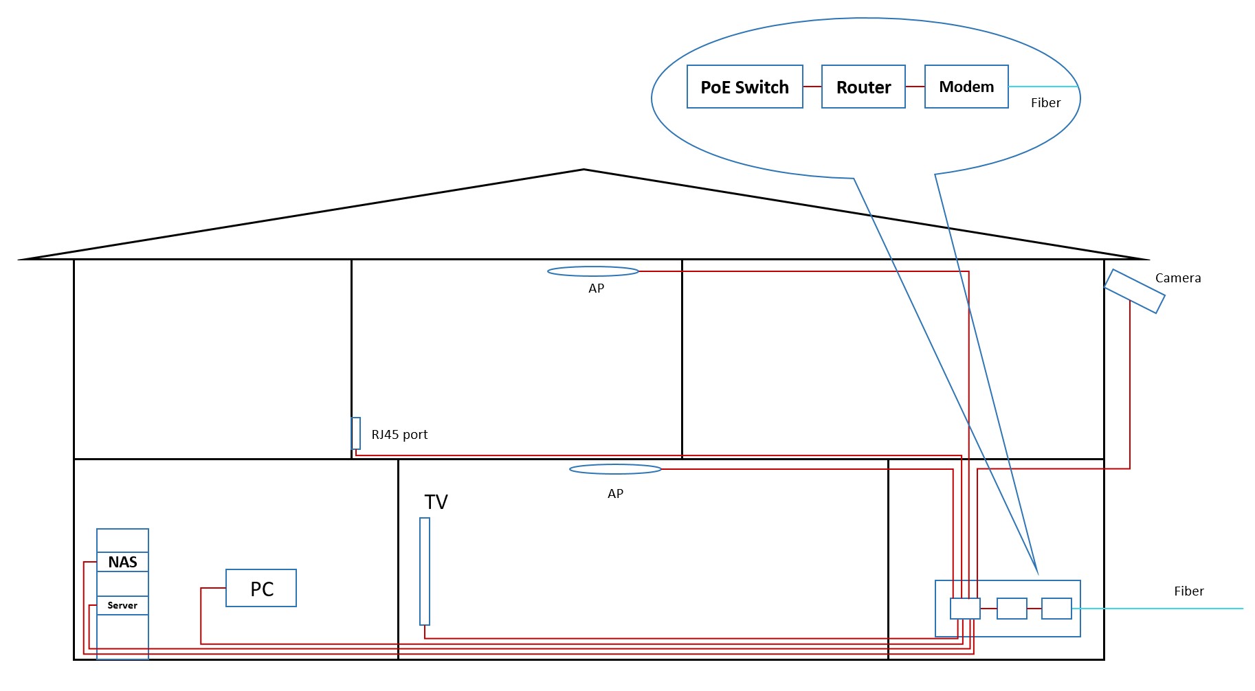
In the example above, the switch is both the hub point for device connectivity and also acts as a PoE switch to provide power to the AP.

After the network planning is complete, all we need is to thread the wires.


home network design


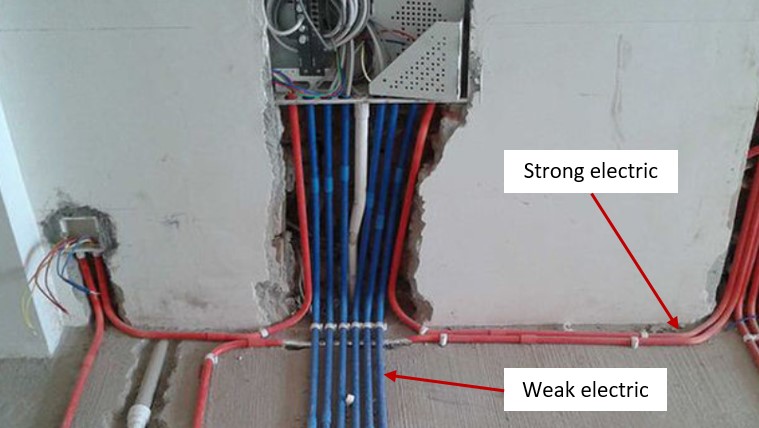
In the previous period, weak electric PVC pipes have been laid, and in order to thread the pipes, we can use some auxiliary threading tools.


home network design


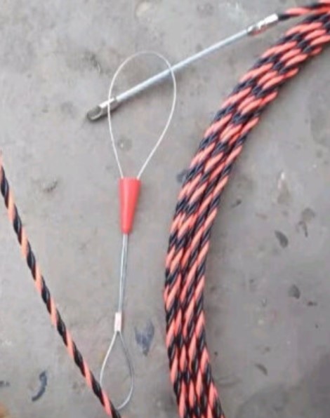
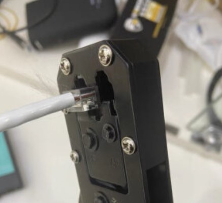
After completing the threading, the next step is to make RJ45 connectors only.

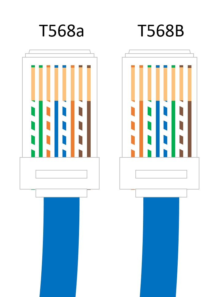
Currently, there are two types of RJ45 connectors, namely T568A and T568B. Since the equipment nowadays can automatically switch between T568A and T568B, you can choose any one of them when making RJ45 connectors.


home network design


home network design


With the above steps, you are basically done with your home network deployment.

If there is anything missing, please add it in the comment section.

Wednesday, December 7, 2022

ONU failure to go online – Problems with ODN

 This actical mainly about problems with ODN and how we can fix it. This is the last article about problems with ODN. In the previous post, I explained – connected connectors of different types and connected fibers of different types.


As I said in the first article about problems with ODN, there are the following problems:

  1. Feeder/distribution/drop fibers are broken,

  2. Dirty optical connectors,

  3. Bent fibers,

  4. Problem with optical splitters,

  5. Connected connectors of different types,

  6. Connected fibers of different types,

  7. Bad splices,

  8. Incorrectly designed networks or incorrectly realized networks.


Today I will explain bad splices and incorrectly designed networks or incorrectly realized networks.


7. Bad splices


There are three types of connection optical fibers: fusion splices, mechanical splices, and optical connectors. Now, I will shortly explain fusion and mechanical splices, bad splices, and the process for fix this problem.


We choose the way of connecting fibers based on: low attenuation, low reflection, and high reliability. In addition, application and price.


The most reliable and commonly used way of connecting fibers is fusion splice. This way of connecting the optical fibers enables low attenuation, low reflection, and high reliability. It is used mainly in the feeder and distribution segments, but also in the drop part of ODN. Generally, wherever on/off fiber is not required.


For fusion splicing, we use a special machine, is fusion splicer. In short, the fibers are prepared using certain tools (e.g. cable slitter, tube cutter, fiber striper, etc.), then cleaning with alcohol or some other liquid for fibers and wipes, then the optical fibers are cut using an optical cleaver. After that, the optical fibers are connected by a fusion connector. In the end, the fusion machine checks the splice: the strength of the joint and evaluates the attenuation.


Mechanical splices are very rarely used. The reason is potentially high attenuation, high reflection, and low reliability. Index matching gel becomes obsolete over time and parameters of the mechanical splice degrades. A mechanical splice is used when we do not have a sufficient number of fusion splicers, when we rarely splice and when there is an emergency intervention. Because that, they are used a little, I will not talk about them and the problems they can cause. That will be one of the new topics.


After short explaining how to connect fibers, I will now explain the most common problems with fusion splices.


There are two main causes of bad splices. Dirty or insufficiently cleaned fibers will deviate during the process of splicing. Another problem is bad to cut fibers. The fiber must be cut at an angle of 90 degrees. This is very important to ensure a quality connection - a little attenuation and little reflection.


Sometimes fusion splicers can make a bad splice. Therefore, the electrodes and software settings should be checked.


Good splice has attenuation about 0.01 dB, max attenuation is 0.1dB. A bad splice may have a greater attenuation than the 0.1dB, values are from 1 to 5 dB. These values of attenuation can disable the connection between Huawei GPON ONT and GPON OLT such as MA5800 OLT. We can see the problem immediately after the splice is completed and repeat the splicing. After finished build the network, we must test all-optical lines by OTDR. With OTDR we can see all incorrect events on the route.


In the next two pictures, we can see the process of fusion splicing (figure 1.) and common cleave problems (figure 2.). In figure 2, there are three common cleave problems: lip, chip, and angle.


sl1


Figure 1. Process of fusion splicing

(https://imedea.uib-csic.es/~salvador/docencia/coms_optiques/addicional/ibm/ch06/06-04.html)


sl.2


Figure 2. Common cleave problems

(https://www.fiberoptics4sale.com/blogs/archive-posts/95049286-fiber-optic-cleaver)


8. Incorrectly designed networks or incorrectly realized network


Sometimes an error is made during design or building and an inadequate optical splitter is installed. In this way, we don`t have the optimal number of fiber divisions. Optical power may be higher or more often lower than required. For example, instead of splitting the fiber 32 times, it is split 16 or 64 times.


We can locate this problem with OTDR or using a PON meter. Incorrect optical power can disable connections between ONUs and OLT. The problem will be fixed when we change the inadequate optical splitter.