Monday, May 30, 2022

Do you know WDM/OTN Latency?

What Is Latency

In a communications network, latency refers to the time it takes for original data to go through a series of processing operations such as encoding on a forwarding device, transmission from the transmit end over transmission links, and reception and decoding on the receive end (destination). The network latency consists of the following parts:

  • Sending latency: The period from the time when the original data enters the forwarding device to the time when the original data completely enters the transmission medium, depending on the data volume/channel bandwidth and processing performance of the devices.

  • Transmission latency: The period from the time when the data is sent from the transmit end to the time when the data is completely received by the receive end, depending on the transmission distance and transmission medium.

  • Processing latency: The period taken by the receive-end device to decode and restore the received information to the original data, depending on the processing performance of the device.

WDM/OTN Latency Distribution

The WDM/OTN network is an optical transmission system that uses optical fibers as the signal transmission media. As shown in the preceding figure, transmission links and physical devices are the main factors affecting network latency in a typical WDM/OTN system.


Figure 1 Typical WDM/OTN network


The latency of physical links is mainly introduced by line fibers and dispersion compensation fibers (DCFs).

  • The latency introduced by line fibers refers to the time it takes for optical signals to transmit over the line fibers.
  • The latency introduced by DCFs refers to the time it takes for optical signals to transmit over the DCFs.

The latency of devices is mainly introduced by electrical- and optical-layer units.

  • The latency introduced by optical-layer units refers to the latency generated when they process optical signals.
  • The latency introduced by electrical-layer units refers to the latency generated when electrical signals converted from optical signals at the receive end undergo a series of operations on the board, such as mapping and forward error correction (FEC) encoding and decoding.

WDM/OTN Latency Performance Optimization Technologies

According to the preceding analysis, the WDM/OTN network latency is mainly introduced by devices and line fibers. The fiber transmission latency accounts for more than 90% of the network latency, followed by device components. Huawei WDM/OTN technology optimizes networking and optical-layer and electrical-layer devices to reduce the end-to-end (E2E) transmission network latency and ensure the minimum network latency.

  • Simplified network architecture design, one-hop service transmission, and reduced latency

The simplified network architecture design reduces forwarding nodes, constructs a one-hop transmission network, and reduces the system latency. For example, the conventional ring or chain topology is optimized to a full-mesh topology during backbone network planning and design. On the metro network, WDM/OTN devices are shifted downwards to CO nodes.

  • Optical-layer optimization:

    • Leverages the coherent communication technology, DCM-free, to eliminate the extra latency caused by DCFs.

    • Replaces the DCF-based dispersion compensation modules with the FBG-based dispersion compensation modules.

    • Leverages the advanced optical-layer technologies of ROADM/OXC to implement optical-layer pass-through and switching, reducing the number of OEO times.

    • Replaces EDFAs with intelligent Raman amplifiers. These Raman amplifiers do not need the erbium-doped fiber as the medium. This avoids extra latency caused by the EDFA, effectively extends the all-optical transmission distance, and reduces the number of electrical regeneration sites.

  • Electrical-layer optimization:

    • Optimizes FEC algorithm performance, increases the transmission distance, and reduces the number of electrical regeneration sites.

    • Flexibly sets the number of FEC levels and reduces the latency penalty.

    • Sets different encapsulation modes for various features.

WDM/OTN Latency Management Solution

Latency management is a comprehensive application based on latency measurement and data estimation of network links and nodes to provide network or service latency that can be sensed, sold, committed, and guaranteed.

Measurable Latency

E2E latency indicators are essential to verification of service level agreements (SLAs) between users and network carriers, especially to latency-sensitive services. Based on the real-time network latency monitoring data, network carriers establish dynamic network latency models and adjust the network transmission policies by predicting latency changes. Therefore, how to obtain the latency data of the transmission link is particularly important.

Traditional methods for measuring the link latency have shortcomings, such as inaccurate precision and service interruption during measurement. For example:

  • Externally connected meters: Services are interrupted during the measurement.

  • Estimation: The transmission latency is estimated based on the lengths of the fiber links at the source and sink ends. This method ignores the latency introduced by the electrical layer and has low precision. In addition, the length of the fiber link is difficult to obtain.

To provide latency-sensitive customers with latency performance priority services, ITU-T G.709 adds the latency measurement function to support online real-time monitoring of network latency. In ITU-T G.709, this function is associated with ODUk PM-layer and TCM-layer overheads. The PM and TCM overheads are latency measurement overheads and located in row 2 and column 3 of the OTU frame. Bit 7 is related to the PM layer test, bits 1 to 6 are related to the TCM layer test, and bit 8 is a reserved bit (the default value is 0). The function is classified into ODUk PM-layer test (DMp) and ODUk TCMi-layer test (DMti). The latency at different TCMi layers can be tested based on the TCMi enable status.

Figure 2 ITU-T G.709-compliant latency overhead bytes


The following figure shows the measurement process.

Figure 3 ITU-T G.709-compliant latency measurement principle
  1. The initiator of latency measurement encapsulates services, inserts the latency measurement bytes into the ODUk overheads, starts the latency measurement, and records the current time.

  2. The latency measurement bytes are transmitted along the links with the services. If an intermediate node exists, the intermediate node transparently transmits the latency measurement bytes and does not process them at the ODUk layer. When the latency measurement bytes reach the terminator of the latency measurement, the latency measurement bytes are transmitted to the initiator in the reverse direction.

  3. The initiator receives the latency measurement bytes from the reverse transmission and compares them with the start time of latency measurement to calculate the round-trip latency from the initiator to terminator. Considering the consistency of WDM/OTN routes, half of the round-trip latency can be regarded as the one-way transmission latency.

This latency measurement is based on ODUk overhead bytes and does not affect services. Therefore, this function provides in-service latency monitoring. The measurement precision is μs-level, which can meet most service requirements. The latency measurement results include the electrical-layer processing latency of service boards and the optical-layer transmission and processing latency of transmission fibers, OA, DCM, and OADM. To ensure the test accuracy, you can perform multiple tests and take the average value.

Thursday, March 10, 2022

How to change acc. and pass of MA5670 Series ONT?

When you get a replacement MA5670 series GPON ONU like MA5671, MA5675, MA5871, you wish amendment its account and arcanum through other ways. this text lists the procedures of adjusting arcanum through online page, interface and BMS.


Changing the root (web) pass:


1. Log in to the online page as root or telecomadmin.

2. Navigate to Account: Maintain -> Account.

ont


3. amendment the pass on the account interface, and click on Apply.


Changing the root(cli) pass:


Change the root(cli) pass through the interface.

1. Connect a laptop to Huawei GPON ONT and log in to the ONT by telnet.

2. Run the set userpasswd root command to vary the pass.


===========================

WAP>set userpasswd root

old password:*****

new password:***********

reenter new password:***********

Password of root has been changed successful!

success!

WAP>

===========================


Change the root(cli) pass through the BMS.


I. (Optional) Add a general ONT VAS profile.

Note: If there's associate ONT VAS profile, choose this profile, right-click, and select Modify from the road menu.


a) From the most menu, select Configuration > Access Profile Management. In the

navigation tree of the tab page that's displayed, select PON Profile > ONT VAS Profile.


b) On the final ONT VAS Profile tab page, right-click, and select Add from the

shortcut menu.

c) within the panel that's displayed, set Name of the final VAS profile, and

configure the WAN port info and voice service parameters for the ONT.

d) Click Next.

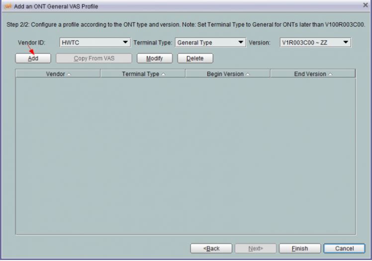
e) within the panel that's displayed, set marketer ID, Terminal sort, and Version,

click Add.

1


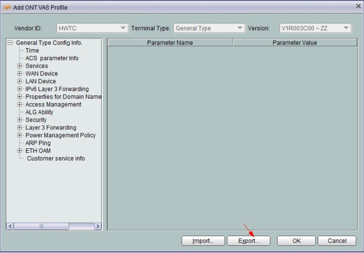
f) within the panel that's displayed, put together parameters of the final ONT VAS

profile supported needs.


II. Export the ONT VAS Profile to be modified.

In the Add ONT VAS Profile panel, click Export to export associate XML configuration file.

2

III. We can use Document (Text) to open the exported XML file.

IV. Add the subsequent contents and save the file.


=============================

<UserInterface>
<X_HW_CLIUserInfo NumberOfInstances=”1>
<X_HW_CLIUserInfoInstance InstanceID=”1” Username=”root” Userpassword=”12345
UserGroup=”” ModifyPWDFlag=”0”/>
</X_HW_CLIUserInfo>
<X_HW_WebUserInfo NumberOfInstances=”1>
<X_HW_WebUserInfoInstance Enable=”1” InstanceID=”2
Password=”UD3F450BF1420B1D1EC4FC28B83634BB” UserLevel=”0
UserName=”e6588EED7B47E466BE215DD0D1239256”/>
</X_HW_WebUserInfo>
</UserInterface>

=============================

Note:


- Fill within the arcanum being modified. The BMS mechanically encrypts the arcanum.

- Username is that the user name and Userpassword is that the arcanum. The user info is modified by dynamic  Username and Userpassword.

- The default user name of a typical user is root. The user name is modified. The common user arcanum within the preceding figure is Admin&123.

V. Import the modified XML file to the BMS.

a. From the most menu, select Configuration > Access Profile Management. within the navigation tree of the tab page that's displayed, select PON Profile > ONT VAS Profile.

b. choose the created profile, right-click, and select Modify from the road menu.

c. within the panel that's displayed, click Next.

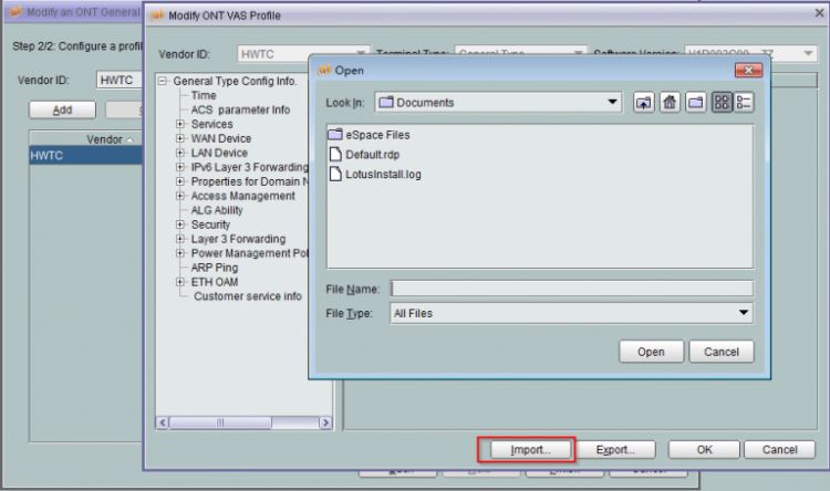
d. choose the record wherever Terminal sort is about to OntGnlrType, right-click, andmchoose Modify from the road menu.

e. within the panel, click Import, and choose the XML configuration file to be foreign within the window that's displayed.

3


f. Click OK.

6. Bind the modified General VAS Profile to the desired ONT.

a. within the Physical Map navigation tree on the most Topology tab page, double-click

the target OLT, or choose the target OLT, right-click, and select NE soul.

b. within the navigation tree, select GPON > GPON Management.

c. within the window on the correct, select GPON ONU.

d. On the GPON ONU tab page, set the search criteria to search out the GPON ONU records.

e. choose associate ONT from the list, right-click, and select Bind General VAS Profile from the road menu. within the panel that's displayed, choose the created profile, and click on okay to complete profile binding.


Changing the telecomadmin pass


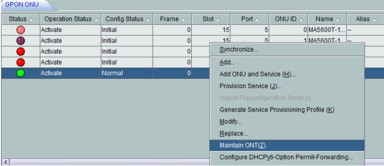
1. Log in to the BMS, choose the ONU whose telecomadmin arcanum must be modified, right-click, and select Maintain ONT(Z).

4

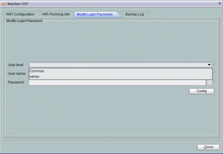
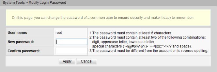
2. In the panel that's displayed, choose Modify Login arcanum.

5

3. choose Admin from the User level drop-down list, input a replacement arcanum in pass, and click on Config.


Thursday, January 20, 2022

Huawei ONT - Mesh Network

We know that Wi-Fi networks have become a necessity for home networking users, and while home broadband services at 100 Mbit/s and up to 1000 Mbit/s are rapidly becoming popularized, it has emerged the need for greater Wi-Fi coverage within a home. Users want access to Wi-FI network in all the amenities of their residence and have a great experience.


To achieve these goals, Huawei has a Mesh solution using the following equipments:


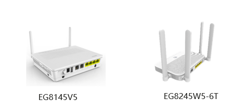
GPON ONT/ONU Gateway EG8145V5 e EG8245W5-6T:


ONTS


ONT Edge WA8021V5


ONT EDGE


Characteristics of a Mesh Network:


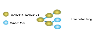
Mesh networking supports flexible Wi-Fi expansion


Supports mesh networking (tree) and two-level cascading distributed networking


tree


Smart Wi-Fi seamless roaming


Supports 802.11k/v and roaming switching within 200 ms


Smart Roaming


Quick self-healing and service recovery within 30s


smart


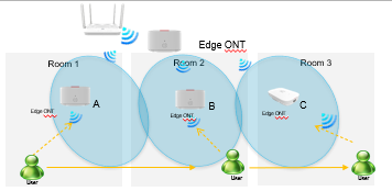
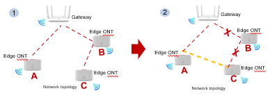
  • Connection along the red dotted lines ensures normal service.

  • When a networking fault occurs, a connection along the yellow dotted lines is established.


How to set up a Mesh network:


*Applicable to connection with Huawei gateways with the latest software version


    1. Configure the  Wi-FI on ONT Home Gateway


    2. Place the edge ONT near a Huawei gateway (within 2 m) and connect the power cable of edge ONT to a socket.


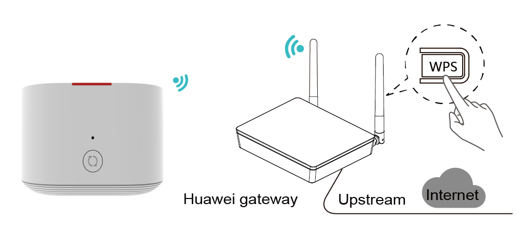
    3. After the edge ONT is powered on, the Huawei gateway can discover edge ONT, and the WPS indicator of the gateway blinks slowly.


    4. Press the WPS button of the gateway once. The WPS indicator and edge ONT indicator change to blink quickly.


Huawei

    5Move the edge ONT to the position where the Wi-Fi coverage is to be expanded. After the indicator is steady white, the edge ONT can access the Internet. No further operation is required.


edge ONT


The Wi-Fi name and password of the edge ONT are automatically synchronized from the Wi-Fi of the Huawei gateway.


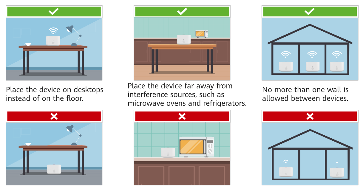
Recommendations for installation Edge ONT:


✔ There are no more than two walls between edge ONTs and the Huawei gateway.


✔ Edge ONTs and the Huawei gateway are placed on the same floor.


  • When the WA8021V5 is connected to a home gateway over the 5 GHz frequency band:


  •  If the signal strength at the WA8021V5 is greater than –65 dBm, the WA8021V5 is placed in a proper position.


  • If the signal strength at the WA8021V5 is less than -73 dBm, you are advised to relocate the WA8021V5 to ensure that the signal strength is greater than -73 dBm.


  • When the WA8021V5 is connected to a home gateway over the 2.4 GHz frequency band:


  • If the signal strength at the WA8021V5 is greater than –65 dBm, the WA8021V5 is placed in a proper position.


  • If the signal strength at the WA8021V5 is less than –65 dBm, you are advised to relocate the WA8021V5 to ensure that the signal strength is greater than –65 dBm.


place