Showing posts with label Huawei switch. Show all posts

Tuesday, November 28, 2023

Why the patch can’t be activated on CE12808?

Issue Description

Can’t activated the patch on CE12808


< -ce12808- >patch load flash:/CE12800-V200R019SPH060.PAT all active

Info: Operating, please wait for a moment.......

Error: The service pack version does not match the system software version.

< -ce12808- >check patch flash:/CE12800-V200R019SPH060.PAT

Warning: Patch package verification consumes system CPU resources. Continue? [Y/N]:y

Info: Prepare to check patch file flash:/CE12800-V200R019SPH060.PAT, please wait....done.

Info: Digital signature verification of the system patch succeeded.


Handling Process

  1. Checked the software version V200R019C00SPC800


  1. When we checked this version, we found it end of support  version


  1. Also when we checked on the system no any patches are available for this end of support version V200R019C00only available versions for V200R019C10.


  1. The patch that you are trying to upload V200R019SPH060, it’s patch for V200R019C10, not for the current version which is running on the switch V200R019C00
  2. That’s why you observed the below error when trying to install the patch

Error: The service pack version does not match the system software version


Root Cause

installing incorrect patch

Solution

The current running software version is end of support, no any available patches for this version.

 advised to upgrade the version and patch to the recommended one. 

Thursday, November 9, 2023

How to Identify Huawei-Certified Switch Optical Modules

  • A switch must use optical or copper modules that have been certified for use on Huawei S switches. Non-certified optical or copper modules cannot ensure transmission reliability and may affect service stability. Huawei is not liable for any problem caused by the use of non-certified optical or copper modules and will not fix such problems.

  • The methods provided here are only for reference. To confirm whether optical modules you are using have been certified for use on Huawei S switches, contact Huawei technical support.

10GE or Lower Speed Optical Modules

Huawei started certification on 10GE or lower speed optical modules for S switch products on July 1, 2013.

To determine whether optical modules delivered for Huawei S switches before July 1, 2013 are certified ones, contact Huawei technical support.

If your optical modules are delivered after July 1, 2013, use either of the following methods to determine whether they have been certified by Huawei.

Method 1: Check for "HUAWEI" on the label

If an optical module has been certified by Huawei, its label contains "HUAWEI", as shown in Figure 10-1.

Figure 10-1 "HUAWEI" on the label of a Huawei-certified S switch optical module

Method 2: Run the command

An optical module has received Huawei S switch certification if it meets the following conditions:

For a device running V200 version:

  • In the display elabel command output, the Manufactured field displays a date later than 2013-07-01.

  • In the display version command output, the displayed version is V200R001C00 or later.

  • In the display transceiver command output, the Vendor Name field displays HUAWEI.

The SFP-FE-SX-MM1310 (part number: 02315233) is a Huawei-certified 100M optical module. However, the Vendor Name field displays the original manufacturer name, instead of HUAWEI.

For copper modules, the Vendor Name field also displays the original manufacturer name, instead of HUAWEI.

25GE, 40GE, and 100GE QSFP28 Optical Modules

Huawei started certification on 25GE, 40GE, and 100GE optical modules for S switch products on January 1, 2016.

To determine whether optical modules delivered for Huawei S switches before January 1, 2016 are certified ones, contact Huawei technical support.

If your optical modules are delivered after January 1, 2016, use either of the following methods to determine whether they have been certified by Huawei.

Method 1: Check for "HUAWEI" on the label

If an optical module has been certified by Huawei, its label contains "HUAWEI", as shown in Figure 10-1.

Method 2: Run the command

A 25GE, 40GE, or 100GE optical module has received Huawei S switch certification if it meets the following conditions:

For a device running V200 version:

  • In the display elabel command output, the Manufactured field displays a date later than 2016-01-01.

  • In the display version command output, the displayed version is V200R008 or later.

  • In the display transceiver command output, the Vendor Name field displays HUAWEI.

For the optical modules connected to high-speed cables or AOC cables, the Vendor Name field displays the original manufacturer name, instead of HUAWEI. For the methods of checking whether such an optical module has been certified by Huawei, contact Huawei technical support personnel.

Wednesday, September 14, 2022

What Is QoS?

QoS improves network resource utilization and allows different types of traffic to compete for network resources based on their priorities, so that voice, video, and important data applications are preferentially processed on network devices.

Importance of QoS

Services on the IP network can be classified into real-time and non-real-time services. Real-time services, such as voice services, occupy fixed bandwidth and are sensitive to network quality changes. Therefore, they have high requirements on network stability. The bandwidth occupied by non-real-time services is unpredictable, and burst traffic often occurs. Burst traffic will deteriorate network quality, cause network congestion, increase the forwarding delay, and even cause packet loss. As a result, service quality deteriorates or even services become unavailable.

Increasing network bandwidth is the best solution, but is costly compared to using a service quality guarantee policy that manages traffic congestion.

QoS is applicable to scenarios where traffic bursts occur and the quality of important services needs to be guaranteed. If service quality requirements are not met for a long time (for example, the service traffic volume exceeds the bandwidth limit for a long time), expand the network capacity or use dedicated devices to control services based on upper-layer applications.

In recent years, traffic of video applications have grown explosively. For enterprises, applications such as HD video conference and HD video surveillance also generate a large amount of HD video traffic on the network. Video traffic occupies more bandwidth than voice traffic. Especially, interactive video applications have high requirements on real-time performance. In addition, with the development of wireless networks, more and more users and enterprises use wireless terminals. The moving of wireless terminals results in more unpredictable traffic on the network. Therefore, the QoS solution design faces more challenges.

QoS Counters

The network quality is affected by the bandwidth of the transmission link, delay and jitter of packet transmission, as well as packet loss rate, which are known as key QoS counters.

Bandwidth

Bandwidth, also called throughput, refers to the maximum number of data bits transmitted between two ends within a specified period (1 second) or the average rate at which specific data flows are transmitted between two network nodes. Bandwidth is expressed in bit/s. There are two common concepts related to bandwidth: uplink rate and downlink rate. The uplink rate refers to the rate at which users send information to a network, and the downlink rate refers to the rate at which a network sends information to users. For example, the rate at which users upload files to a network is determined by the uplink rate, and the rate at which users download files is determined by the downlink rate.

Delay

Delay refers to the time required to transmit a packet or a group of packets from the transmit end to the receive end. It consists of the transmission delay and processing delay. Voice transmission is used as an example. A delay refers to the period from when words are spoken to when they are heard. Generally, people are insensitive to a delay of less than 100 ms. If a delay is the range of 100 ms to 300 ms, both parties of the call can sense slight pauses in the peer party's reply, which may seem annoying to both. If a delay is longer than 300 ms, both the speaker and responder obviously sense the delay and have to wait for responses. If the speaker cannot wait and repeats what has been said, voices overlap and the quality of the conversation deteriorates severely.

Jitter

If network congestion occurs, the delays of packets over the same connection are different. The jitter is used to describe the degree of delay change, that is, the time difference between the maximum delay and the minimum delay. Jitter is an important parameter for real-time transmission, especially for real-time services, such as voice and video, which are intolerant to the jitter because the jitter will cause voice or video interruptions. The jitter also affects protocol packet transmission. Some protocols send interactive packets at a fixed interval. If the jitter is too large, protocol flapping occurs. Jitter is prevalent on networks but generally does not affect service quality if it does not exceed a specific tolerance. The buffer can overcome the excessive jitter, but it will increase the delay.

Packet Loss Rate

The packet loss rate refers to the percentage of the number of packets lost during data transmission to the total number of packets sent. Slight packet loss does not affect services. For example, users are unaware of the loss of a bit or a packet in voice transmission. The loss of a bit or a packet in video transmission may cause the image on the screen to become garbled instantly, but the image can be restored quickly. TCP can be used to transmit data to handle slight packet loss because TCP allows the lost packets to be retransmitted. If severe packet loss does occur, the packet transmission efficiency is affected. QoS focuses on the packet loss rate. The packet loss rate must be controlled within a certain range during transmission.

Application Scenarios of QoS

Take enterprise office as an example. In addition to the basic web browsing and email services, services such as Telnet-based device login, remote video conferences, real-time voice calls, FTP file upload and download, and video playback must also have their network quality guaranteed during busy hours. If services have varying network quality requirements, you can configure corresponding QoS functions or enable QoS only for some services to meet the requirements.

qos

  • Network protocols and management protocols: such as OSPF and Telnet

    These services require low delay and low packet loss rate, but do not require high bandwidth. To meet the requirements of such services, configure priority mapping to map the priority of the service packets into a higher CoS value so that the network device can preferentially forward the packets.

  • Real-time services: such as video conference and VoIP

    Video conferences require high bandwidth, low delay, and low jitter. To meet the requirements of such services, configure traffic policing to provide high bandwidth for video packets and priority mapping to increase the priority of video packets.

    VoIP refers to the real-time voice call over the IP network. It requires low packet loss, delay, and jitter. If these requirements cannot be met, both parties of a call will suffer from poor call quality. To resolve this problem, configure priority mapping so that voice packets take precedence over video packets and configure traffic policing to provide the maximum bandwidth for voice packets. This ensures that voice packets are preferentially forwarded in the case of network congestion.

  • Heavy-traffic services: such as FTP, database backup, and file dump

    Heavy-traffic services refer to network services in which a large amount of data is transmitted for a long time. Such services require a low packet loss rate. To meet the requirements of such services, configure traffic shaping to cache the service packets sent from an interface in the data buffer. This reduces packet loss upon congestion caused by burst traffic.

  • Streaming media: such as online audio playback and video on demand (VOD)

    Users can cache audio and video programs before playing them, reducing requirements on the network delay, packet loss, and jitter. To reduce the packet loss rate and delay of these services, configure priority mapping to increase the priority of the service packets.

  • Common services: such as HTML web page browsing and email

    Common services have no special requirements on the network. You do not need to deploy QoS for them.

Service Models

How are QoS indicators defined within proper ranges to improve network service quality? The answer lies in the QoS model. QoS is an overall solution, instead of being merely a single function. When two hosts on a network communicate with each other, traffic between them may traverse a large number of devices. QoS can guarantee E2E service quality only when all devices on the network use a unified QoS service model.

The following describes the three mainstream QoS models. Huawei switches, routers, firewalls, and WLAN devices support QoS based on Differentiated Services (DiffServ), which is the most commonly used.

Best-Effort

Best-Effort is the default service model for the Internet and applies to various network applications, such as FTP and email. It is the simplest service model, in which an application can send any number of packets at any time without notifying the network. The network then makes the best effort to transmit the packets but provides no guarantee of performance in terms of delay and reliability. The Best-Effort model is suitable for services that have low requirements for delay and packet loss rate.

Integrated Service (IntServ)

In the IntServ model, an application uses a signaling protocol to notify the network of its traffic parameters and apply for a specific level of QoS before sending packets. The network reserves resources for the application based on the traffic parameters. After the application receives an acknowledgement message and confirms that sufficient resources have been reserved, it starts to send packets within the range specified by the traffic parameters. The network maintains a state for each packet flow and performs QoS behaviors based on this state to guarantee application performance.

The IntServ model uses Resource Reservation Protocol (RSVP) for signaling. Resources such as bandwidth and priority are reserved on a known path, and each network element along the path must reserve required resources for data flows requiring QoS guarantee. Each network element checks whether sufficient resources can be reserved based on these RSVP messages. The path is available only when all involved network elements can provide sufficient resources.

DiffServ

DiffServ classifies packets on a network into multiple classes and provides differentiated processing for each class. In this way, when congestion occurs, classes with a higher priority are given preference. Packets of the same class are aggregated and sent as a whole to ensure the same delay, jitter, and packet loss rate.

In the DiffServ model, traffic classification and aggregation are completed on border nodes. A border node flexibly classifies packets based on a combination of different fields (such as the source and destination addresses, priority in the ToS field, and protocol type), and marks different classes of packets with appropriate priority values. Other nodes only need to identify these markings to allocate resources and control traffic.

Unlike the IntServ model, the DiffServ model does not require a signaling protocol. In this model, an application does not need to apply for network resources before sending packets. Instead, the application sets QoS parameters in the packets, through which the network can learn the QoS requirements of the application. The network provides differentiated services based on the QoS parameters of each data flow and does not need to maintain a state for each data flow. DiffServ takes full advantage of IP networks' flexibility and extensibility and transforms information in packets into per-hop behaviors (PHBs), greatly reducing signaling operations.

Mechanisms in the DiffServ Model

The DiffServ model involves the following QoS mechanisms:

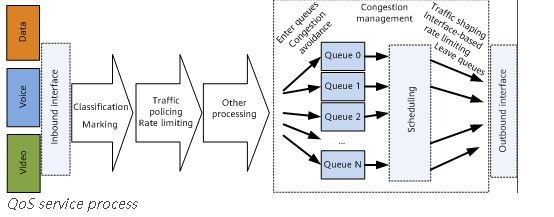
  • Traffic classification and marking

    Traffic classification and marking are prerequisites for implementing differentiated services. Traffic classification divides packets into different classes, and can be implemented using traffic classifiers configured using Modular QoS Command-Line Interface (MQC). Traffic marking sets different priorities for packets and can be implemented through priority mapping and re-marking. Packets carry different types of precedence field depending on the network type. For example, packets carry the 802.1p field in a VLAN network, the EXP field on an MPLS network, and the DSCP field on an IP network.

  • Traffic policing, traffic shaping, and interface-based rate limiting

    Traffic policing and traffic shaping control the traffic rate within a bandwidth limit. Traffic policing drops excess traffic when the traffic rate exceeds the limit, whereas traffic shaping buffers excess traffic. Traffic policing and traffic shaping can be performed on an interface to implement interface-based rate limiting.

  • Congestion management and congestion avoidance

    Congestion management buffers packets in queues upon network congestion and determines the forwarding order using a specific scheduling algorithm. Congestion avoidance monitors network resource usage and drops packets to mitigate network overloading when congestion worsens.

Traffic classification and marking are the basis of differentiated services. Traffic policing, traffic shaping, interface-based rate limiting, congestion management, and congestion avoidance control network traffic and resource allocation to implement differentiated services.

The following figure shows the QoS service process on network devices.

qs

QoS vs. HQoS

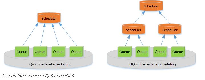
Traditional QoS technologies can provide differentiated services to meet requirements of voice, video, and data services. As the number of users and their individual bandwidth consumptions continue to grow, these technologies are facing new problems, including:
  • Traffic is scheduled based on interface bandwidth, allowing differentiation of traffic based on service levels. However, it is difficult to differentiate services based on users. Therefore, traditional QoS is typically applied to the core layer, instead of the access layer.

  • Traditional QoS cannot manage or schedule traffic of multiple services for multiple users simultaneously.

Hierarchical Quality of Service (HQoS) has been introduced to address these issues by differentiating traffic of different users and scheduling traffic based on service priorities. HQoS uses multiple levels of queues to further differentiate service traffic, and provides uniform management and hierarchical scheduling for transmission objects such as users and services. It enables network devices to control internal resources, providing QoS guarantee for VIP users while reducing network construction costs.

q

Sunday, June 12, 2022

Why ICMP delay with jumbo frames between Huawei and Cisco switch?

This case mainly talks about the ICMP delay caused by the packet processing mechanism of the CE switch.

Problem Description

The CE12808 switch is connected to the CRS_Router Cisco switch through four Layer 3 interfaces. After the interconnection, it's found that the ICMP delay between the two devices is long.


imgDownload?uuid=bd70c794892a43068942105


To check whether the link is normal, we make an ICMP test with large Packets and see the following on Huawei & Cisco.


1. From Huawei to Cisco :

~Huawei]ping -m 30 -t 8000 -c 100 -s 9152 -a  192.168.23.2 -f  192.168.23.1 

  PING 192.168.23.1: 9152  data bytes, press CTRL_C to break

    Reply from 192.168.23.1: bytes=9152 Sequence=1 ttl=255 time=5 ms

    Reply from 192.168.23.1: bytes=9152 Sequence=2 ttl=255 time=6 ms

    Reply from 192.168.23.1: bytes=9152 Sequence=3 ttl=255 time=3 ms

    Reply from 192.168.23.1: bytes=9152 Sequence=4 ttl=255 time=3 ms

    Reply from 192.168.23.1: bytes=9152 Sequence=9 ttl=255 time=17 ms

    Reply from 192.168.23.1: bytes=9152 Sequence=10 ttl=255 time=59 ms

    Reply from 192.168.23.1: bytes=9152 Sequence=11 ttl=255 time=93 ms

    Reply from 192.168.23.1: bytes=9152 Sequence=12 ttl=255 time=93 ms

    Reply from 192.168.23.1: bytes=9152 Sequence=13 ttl=255 time=93 ms

    Reply from 192.168.23.1: bytes=9152 Sequence=14 ttl=255 time=92 ms

    Reply from 192.168.23.1: bytes=9152 Sequence=15 ttl=255 time=93 ms

                                      ...

    Reply from 192.168.23.1: bytes=9152 Sequence=24 ttl=255 time=92 ms

    Reply from 192.168.23.1: bytes=9152 Sequence=25 ttl=255 time=93 ms


  --- 192.168.23.1 ping statistics ---

    100 packet(s) transmitted

    100 packet(s) received

    0.00% packet loss

    round-trip min/avg/max = 3/84/94 ms


2. From Cisco to Huawei :


Cisco# ping   192.168.24.2 source   192.168.24.1 size 9180 donotfrag count 30000 interval 5


Fri Jul  1 03:50:57.844 GMT


Type escape sequence to abort.


Sending 30000, 9180-byte ICMP Echos to 192.168.24.2, timeout is 2 seconds:


Success rate is 100 percent (153/153), round-trip min/avg/max = 1/90/94 ms


There seems to be some ISSUE on the link interconnect because the delay should not exceed 15 or 20 ms.

Handling Process

Before checking the issue we need to be clear about MTU for Cisco & Huawei:

A. Cisco Interface MTU is 9194: The ICMP test packet length is 9180 bytes through Cisco CRS Ios XR not consider 14 bytes for Ethernet on ICMP Test.

B. Huawei Interface MTU is 9180: The ICMP test packet length is 9152 bytes through  Huawei does not consider 14 bytes for Ethernet, 8 bytes for ICMP, and 6 bytes for VLAN.

1. At the beginning of the issue, we thought the issue was on Optical Fibers and GE 10G Transceivers, so our plan was to verify physical links and made physical loops for verifying the Transceiver. After this, the issue continues.

[~Huawei]display interface 10GE8/0/46  transceiver  verbose  | in DBm

   Current RX Power (dBm)                :-2.79

   Default RX Power High Threshold (dBm) :2.50

   Default RX Power Low Threshold (dBm)  :-16.40

   Current TX Power (dBm)                :-3.75

   Default TX Power High Threshold (dBm) :2.50

   Default TX Power Low Threshold (dBm)  :-10.20

Cisco Ten 0/4/0/0 <<>> Huawei 10GE5/0/46

Cisco#sh controllers tenGigE 0/4/0/0 phy  | in dBm

Fri Jul  1 03:18:00.095 GMT

                Tx power: -3 dBm (4307 in units of 0.1 uW)

                Rx power: -5 dBm (2597 in units of 0.1 uW)


<Huawei>display  interface 10GE5/0/46  transceiver verbose  | in dBm

   Current RX Power (dBm)                :-3.90

   Default RX Power High Threshold (dBm) :2.50

   Default RX Power Low Threshold (dBm)  :-16.40

   Current TX Power (dBm)                :-3.26

   Default TX Power High Threshold (dBm) :2.50

   Default TX Power Low Threshold (dBm)  :-10.20


2. Verify the packets for ICMP statistics and check if there is some issue with processing :


<Huawei>disp current-configuration configuration include-default | i fast

undo arp fast-reply disable

undo icmp echo-reply fast disable


[~Huawei]display icmp fast-reply statistics slot 5

------------------------ Display ICMP Statistics -------------------------------

Received packets:                                                              

     request packets:                             0                            

     invalid request packets:                     0                            

     failed to get vrf:                           0                            

     destination is not host ip:                  0                            

     failed to get ctrl word:                     0                            

Send packets:                                                                   

     successful reply packets:                    0                            

     failed reply packets:                        0                            


[~Huawei]display icmp fast-reply statistics slot 8

------------------------ Display ICMP Statistics -------------------------------

Received packets:                                                               

     request packets:                             0                            

     invalid request packets:                     0                            

     failed to get vrf:                           0                            

     destination is not host ip:                  0                            

     failed to get ctrl word:                     0                            

Send packets:                                                                  

     successful reply packets:                    0                            

     failed reply packets:                        0                            


[~Huawei]display icmp fast-reply statistics slot 1


------------------------ Display ICMP Statistics -------------------------------

Received packets:                                                              

     request packets:                             0                             

     invalid request packets:                     0                            

     failed to get vrf:                           0                            

     destination is not host ip:                  0                             

     failed to get ctrl word:                     0                            

Send packets:                                                                  

     successful reply packets:                    0                            

     failed reply packets:                        0                            

--------------------------------------------------------------------------------


[~Huawei]display icmp fast-reply statistics slot 4

------------------------ Display ICMP Statistics -------------------------------

Received packets:                                                              

     request packets:                             0                            

     invalid request packets:                     0                            

     failed to get vrf:                           0                            

     destination is not host ip:                  0                            

     failed to get ctrl word:                     0                             

Send packets:                                                                  

     successful reply packets:                    0                            

     failed reply packets:                        0                            

--------------------------------------------------------------------------------

Root Cause

The Ping Packet Processing on a CE Switch is like follows :

imgDownload?uuid=218fdfcb05dc45c28d3e53b

1. The green line in the preceding figure shows ping packet processing. The forwarding plane sends ping packets to the control plane through the CPU. The processing latency mainly includes the latency on the forwarding plane and the latency on the control plane. The latency on the forwarding plane is at the microsecond level and can be ignored. The latency on the control plane is determined by the CPU usage. If the CPU usage is high, the latency increases.

2. The red lines show service data flow processing. Service data packets are directly forwarded by the forwarding plane and are not processed by the control plane. The latency is at the microsecond level.

Analysis of Latency and Jitter During Ping Packet Transmission Between CE and Cisco Switches :

Ping packet processing is as follows:

1.  The packet receiving process on the CE switch is as follows:

Control plane of the Cisco switch -> packet sending by the CPU of the Cisco switch -> forwarding plane of the Cisco switch -> forwarding plane of the CE switch -> packet receiving by the CPU of the CE switch -> control plane of the CE switch

2. The packet forwarding process on the CE switch is as follows:

Control plane of the CE switch -> packet sending by the CPU of the CE switch -> forwarding plane of the CE switch -> forwarding plane of the Cisco switch -> packet receiving by the CPU of the Cisco switch -> control plane of the Cisco switch.

Solution

The latency of ping packets mainly includes the processing latency on the Cisco switch and the processing latency on the CE switch. The processing latency on the CE switch mainly includes the latency on the forwarding plane and the latency on the control plane.

The latency on the forwarding plane is at the microsecond level and can be ignored. The latency on the control plane is determined by the CPU usage. If the CPU usage is high, the latency increases.

Because of the CPU performance and software calculation priority of the CE switch, a little latency and jitter may occur for ping packets that need to be processed by the CPU. However, data packet forwarding is not affected on the CE switch because data packets are forwarded by the hardware and software processing is not involved.

Suggestions and Summary

As we mentioned this issue is just related to IMCP Test, not with Traffic of Services.

That's true because when we put traffic on the Internet there is no issue with users.

Before the ICMP test, ensure that the test does not affect service traffic processing.