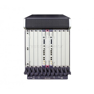
Showing posts with label HUAWEI Router. Show all posts

Monday, February 26, 2024

How to Logging In to NetEngine 8000 M by Using the Console Interface?

When setting up a local configuration environment with the console interface being used, you can log in to the NetEngine 8100 M, NetEngine 8000E M, NetEngine 8000 M Series by using the terminal emulation program on the PC.

Prerequisites

Figure 1 Networking diagram of logging in to the NetEngine 8100 M, NetEngine 8000E M, NetEngine 8000 M by using the console interface

  • The NetEngine 8100 M, NetEngine 8000E M, NetEngine 8000 M is powered on and works properly.

  • The PC is connected to the NetEngine 8100 M, NetEngine 8000E M, NetEngine 8000 M through asynchronous interfaces.

  • Installing terminal emulation program on the PC (such as PuTTY.exe)

Perform the following configurations on the terminal emulation program on the PC.

The console port applies the non-standard serial port communication cable sequence. For more information, see ETH/OAM Management Cables in Hardware Description.

Procedure

  1. Use a serial cable to connect the serial interface on the PC and the console interface on the NetEngine 8100 M, NetEngine 8000E M, NetEngine 8000 M.

    For details about the console interface, see the NetEngine 8100 M, NetEngine 8000E M, NetEngine 8000 M Hardware Description.

    If a third-party USB-to-RJ45 serial cable is used, it is recommended that the cable length be less than or equal to 2 m to ensure signal integrity.

  2. Start the terminal emulation program such as PuTTY.exe on the PC.
  3. On the PuTTY configuration page (shown in Figure 2), set the connection type to Serial.

    Figure 2 PuTTY configuration page

  4. Select Serial under Connection from the left navigation tree on the PuTTY configuration page. On the page shown in Figure 3, set communication parameters of the port to be consistent with those on the device. (The following figure is for reference only. Use the default settings during configuration.)

    Figure 3 PuTTY configuration page

  5. Click Open. Then the system prompts you to set an authentication password, as shown in Figure 4. After the confirm the password, the system automatically saves it.

    Figure 4 Login page

Commissioning Result

After the password is set, the command prompt (for example, <HUAWEI>) of the user view is displayed, which indicates that you have entered the user view and can perform configurations.

You can enter commands to configure the router or view its running status. Enter a question mark (?) when you need help.

  • A password is entered in man-machine interaction mode. The system does not display the entered password.

  • A password is a string of 8 to 16 case-sensitive characters and must contain at least two types of the following characters: uppercase letters, lowercase letters, digits, and special characters.

    Special characters do not include question marks (?) or spaces. However, when double quotation marks are used around a password, spaces are allowed in the password.
    • Double quotation marks cannot contain double quotation marks if spaces are used in a password.
    • Double quotation marks can contain double quotation marks if no space is used in a password.

    For example, the password "Aa123"45"" is valid, but the password "Aa 123"45"" is invalid.

The configured password is displayed in ciphertext in the configuration file.

If the login fails, click Disconnect and then Call. If the login still fails, repeat Step 1 to check whether the parameters or physical connections are correct. If they are correct, log in to the NetEngine 8100 M, NetEngine 8000E M, NetEngine 8000 M again.

Wednesday, September 14, 2022

What Is QoS?

QoS improves network resource utilization and allows different types of traffic to compete for network resources based on their priorities, so that voice, video, and important data applications are preferentially processed on network devices.

Importance of QoS

Services on the IP network can be classified into real-time and non-real-time services. Real-time services, such as voice services, occupy fixed bandwidth and are sensitive to network quality changes. Therefore, they have high requirements on network stability. The bandwidth occupied by non-real-time services is unpredictable, and burst traffic often occurs. Burst traffic will deteriorate network quality, cause network congestion, increase the forwarding delay, and even cause packet loss. As a result, service quality deteriorates or even services become unavailable.

Increasing network bandwidth is the best solution, but is costly compared to using a service quality guarantee policy that manages traffic congestion.

QoS is applicable to scenarios where traffic bursts occur and the quality of important services needs to be guaranteed. If service quality requirements are not met for a long time (for example, the service traffic volume exceeds the bandwidth limit for a long time), expand the network capacity or use dedicated devices to control services based on upper-layer applications.

In recent years, traffic of video applications have grown explosively. For enterprises, applications such as HD video conference and HD video surveillance also generate a large amount of HD video traffic on the network. Video traffic occupies more bandwidth than voice traffic. Especially, interactive video applications have high requirements on real-time performance. In addition, with the development of wireless networks, more and more users and enterprises use wireless terminals. The moving of wireless terminals results in more unpredictable traffic on the network. Therefore, the QoS solution design faces more challenges.

QoS Counters

The network quality is affected by the bandwidth of the transmission link, delay and jitter of packet transmission, as well as packet loss rate, which are known as key QoS counters.

Bandwidth

Bandwidth, also called throughput, refers to the maximum number of data bits transmitted between two ends within a specified period (1 second) or the average rate at which specific data flows are transmitted between two network nodes. Bandwidth is expressed in bit/s. There are two common concepts related to bandwidth: uplink rate and downlink rate. The uplink rate refers to the rate at which users send information to a network, and the downlink rate refers to the rate at which a network sends information to users. For example, the rate at which users upload files to a network is determined by the uplink rate, and the rate at which users download files is determined by the downlink rate.

Delay

Delay refers to the time required to transmit a packet or a group of packets from the transmit end to the receive end. It consists of the transmission delay and processing delay. Voice transmission is used as an example. A delay refers to the period from when words are spoken to when they are heard. Generally, people are insensitive to a delay of less than 100 ms. If a delay is the range of 100 ms to 300 ms, both parties of the call can sense slight pauses in the peer party's reply, which may seem annoying to both. If a delay is longer than 300 ms, both the speaker and responder obviously sense the delay and have to wait for responses. If the speaker cannot wait and repeats what has been said, voices overlap and the quality of the conversation deteriorates severely.

Jitter

If network congestion occurs, the delays of packets over the same connection are different. The jitter is used to describe the degree of delay change, that is, the time difference between the maximum delay and the minimum delay. Jitter is an important parameter for real-time transmission, especially for real-time services, such as voice and video, which are intolerant to the jitter because the jitter will cause voice or video interruptions. The jitter also affects protocol packet transmission. Some protocols send interactive packets at a fixed interval. If the jitter is too large, protocol flapping occurs. Jitter is prevalent on networks but generally does not affect service quality if it does not exceed a specific tolerance. The buffer can overcome the excessive jitter, but it will increase the delay.

Packet Loss Rate

The packet loss rate refers to the percentage of the number of packets lost during data transmission to the total number of packets sent. Slight packet loss does not affect services. For example, users are unaware of the loss of a bit or a packet in voice transmission. The loss of a bit or a packet in video transmission may cause the image on the screen to become garbled instantly, but the image can be restored quickly. TCP can be used to transmit data to handle slight packet loss because TCP allows the lost packets to be retransmitted. If severe packet loss does occur, the packet transmission efficiency is affected. QoS focuses on the packet loss rate. The packet loss rate must be controlled within a certain range during transmission.

Application Scenarios of QoS

Take enterprise office as an example. In addition to the basic web browsing and email services, services such as Telnet-based device login, remote video conferences, real-time voice calls, FTP file upload and download, and video playback must also have their network quality guaranteed during busy hours. If services have varying network quality requirements, you can configure corresponding QoS functions or enable QoS only for some services to meet the requirements.
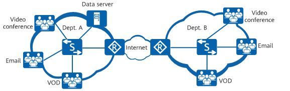
qos

  • Network protocols and management protocols: such as OSPF and Telnet

    These services require low delay and low packet loss rate, but do not require high bandwidth. To meet the requirements of such services, configure priority mapping to map the priority of the service packets into a higher CoS value so that the network device can preferentially forward the packets.

  • Real-time services: such as video conference and VoIP

    Video conferences require high bandwidth, low delay, and low jitter. To meet the requirements of such services, configure traffic policing to provide high bandwidth for video packets and priority mapping to increase the priority of video packets.

    VoIP refers to the real-time voice call over the IP network. It requires low packet loss, delay, and jitter. If these requirements cannot be met, both parties of a call will suffer from poor call quality. To resolve this problem, configure priority mapping so that voice packets take precedence over video packets and configure traffic policing to provide the maximum bandwidth for voice packets. This ensures that voice packets are preferentially forwarded in the case of network congestion.

  • Heavy-traffic services: such as FTP, database backup, and file dump

    Heavy-traffic services refer to network services in which a large amount of data is transmitted for a long time. Such services require a low packet loss rate. To meet the requirements of such services, configure traffic shaping to cache the service packets sent from an interface in the data buffer. This reduces packet loss upon congestion caused by burst traffic.

  • Streaming media: such as online audio playback and video on demand (VOD)

    Users can cache audio and video programs before playing them, reducing requirements on the network delay, packet loss, and jitter. To reduce the packet loss rate and delay of these services, configure priority mapping to increase the priority of the service packets.

  • Common services: such as HTML web page browsing and email

    Common services have no special requirements on the network. You do not need to deploy QoS for them.

Service Models

How are QoS indicators defined within proper ranges to improve network service quality? The answer lies in the QoS model. QoS is an overall solution, instead of being merely a single function. When two hosts on a network communicate with each other, traffic between them may traverse a large number of devices. QoS can guarantee E2E service quality only when all devices on the network use a unified QoS service model.

The following describes the three mainstream QoS models. Huawei switches, routers, firewalls, and WLAN devices support QoS based on Differentiated Services (DiffServ), which is the most commonly used.

Best-Effort

Best-Effort is the default service model for the Internet and applies to various network applications, such as FTP and email. It is the simplest service model, in which an application can send any number of packets at any time without notifying the network. The network then makes the best effort to transmit the packets but provides no guarantee of performance in terms of delay and reliability. The Best-Effort model is suitable for services that have low requirements for delay and packet loss rate.

Integrated Service (IntServ)

In the IntServ model, an application uses a signaling protocol to notify the network of its traffic parameters and apply for a specific level of QoS before sending packets. The network reserves resources for the application based on the traffic parameters. After the application receives an acknowledgement message and confirms that sufficient resources have been reserved, it starts to send packets within the range specified by the traffic parameters. The network maintains a state for each packet flow and performs QoS behaviors based on this state to guarantee application performance.

The IntServ model uses Resource Reservation Protocol (RSVP) for signaling. Resources such as bandwidth and priority are reserved on a known path, and each network element along the path must reserve required resources for data flows requiring QoS guarantee. Each network element checks whether sufficient resources can be reserved based on these RSVP messages. The path is available only when all involved network elements can provide sufficient resources.

DiffServ

DiffServ classifies packets on a network into multiple classes and provides differentiated processing for each class. In this way, when congestion occurs, classes with a higher priority are given preference. Packets of the same class are aggregated and sent as a whole to ensure the same delay, jitter, and packet loss rate.

In the DiffServ model, traffic classification and aggregation are completed on border nodes. A border node flexibly classifies packets based on a combination of different fields (such as the source and destination addresses, priority in the ToS field, and protocol type), and marks different classes of packets with appropriate priority values. Other nodes only need to identify these markings to allocate resources and control traffic.

Unlike the IntServ model, the DiffServ model does not require a signaling protocol. In this model, an application does not need to apply for network resources before sending packets. Instead, the application sets QoS parameters in the packets, through which the network can learn the QoS requirements of the application. The network provides differentiated services based on the QoS parameters of each data flow and does not need to maintain a state for each data flow. DiffServ takes full advantage of IP networks' flexibility and extensibility and transforms information in packets into per-hop behaviors (PHBs), greatly reducing signaling operations.

Mechanisms in the DiffServ Model

The DiffServ model involves the following QoS mechanisms:

  • Traffic classification and marking

    Traffic classification and marking are prerequisites for implementing differentiated services. Traffic classification divides packets into different classes, and can be implemented using traffic classifiers configured using Modular QoS Command-Line Interface (MQC). Traffic marking sets different priorities for packets and can be implemented through priority mapping and re-marking. Packets carry different types of precedence field depending on the network type. For example, packets carry the 802.1p field in a VLAN network, the EXP field on an MPLS network, and the DSCP field on an IP network.

  • Traffic policing, traffic shaping, and interface-based rate limiting

    Traffic policing and traffic shaping control the traffic rate within a bandwidth limit. Traffic policing drops excess traffic when the traffic rate exceeds the limit, whereas traffic shaping buffers excess traffic. Traffic policing and traffic shaping can be performed on an interface to implement interface-based rate limiting.

  • Congestion management and congestion avoidance

    Congestion management buffers packets in queues upon network congestion and determines the forwarding order using a specific scheduling algorithm. Congestion avoidance monitors network resource usage and drops packets to mitigate network overloading when congestion worsens.

Traffic classification and marking are the basis of differentiated services. Traffic policing, traffic shaping, interface-based rate limiting, congestion management, and congestion avoidance control network traffic and resource allocation to implement differentiated services.

The following figure shows the QoS service process on network devices.
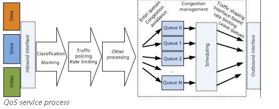
qs

QoS vs. HQoS

Traditional QoS technologies can provide differentiated services to meet requirements of voice, video, and data services. As the number of users and their individual bandwidth consumptions continue to grow, these technologies are facing new problems, including:
  • Traffic is scheduled based on interface bandwidth, allowing differentiation of traffic based on service levels. However, it is difficult to differentiate services based on users. Therefore, traditional QoS is typically applied to the core layer, instead of the access layer.

  • Traditional QoS cannot manage or schedule traffic of multiple services for multiple users simultaneously.

Hierarchical Quality of Service (HQoS) has been introduced to address these issues by differentiating traffic of different users and scheduling traffic based on service priorities. HQoS uses multiple levels of queues to further differentiate service traffic, and provides uniform management and hierarchical scheduling for transmission objects such as users and services. It enables network devices to control internal resources, providing QoS guarantee for VIP users while reducing network construction costs.
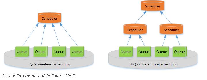
q

Thursday, April 29, 2021

How to checking the Temperature of Each Board on Huawei Router?

 This section describes how to verify Huawei router like NE40E ME60-X8 boards temperature

Prerequisites

The router has been logged in to.

Procedure

  1. Run the display temperature[ [ lpu | mpu | sfu ] slot slot-id [ pic pic-id ] ] command to view the temperature status on each board

    <HUAWEI> display temperature
    SlotID2
     Base-Board, Unit:C, Slot2
    PCB   I2C Addr Chl  Status  Minor Major Fatal Adj_speed Temp
                                                  TMin Tmax (C)
    -----------------------------------------------------------------
    LPUF  1   1    0    NORMAL  70    80    90    60   70   36
    LPUF  1   2    0    NORMAL  60    70    80    50   60   33
    LPUF  1   4    0    NORMAL  70    80    90    60   70   35
    LPUF  1   5    0    NORMAL  80    90    100   70   80   39
    LPUF  1   6    0    NORMAL  70    80    90    60   70   38
    LPUF  2   76   1    NORMAL  90    96    102   80   90   39
    LPUF  2   76   2    NORMAL  90    96    102   80   90   40
    TCMB  1   3    0    NORMAL  70    80    90    60   70   34
    TCMB  1   7    0    NORMAL  60    70    80    50   60   31

    Pay attention to the values of boldfaced fields displayed. The Temp(C) field indicates the current temperature. The Minor field indicates the threshold of a high temperature for a minor alarm. The Major field indicates the threshold of a high temperature for a major alarm. The Fatal field indicates the threshold of a high temperature for a critical alarm. If the board temperature reaches or exceeds the value of the Fatal field, Huawe ME60 may work abnormally or be damaged.

    If the displayed value of the Temp(C) field is lower than that of the Minor field, the board temperature is normal. Then, go on with the subsequent commissioning.

Troubleshooting

If the board temperature exceeds the threshold, perform the following operations:

  1. Check whether fans are faulty and replace any faulty fans.

  2. Check whether the air filter is clogged. If it is clogged, clean it.

  3. Check whether the ambient temperature is too high. If the ambient temperature is too high, lower the temperature in the equipment room.

  4. If the board temperature is still high after the preceding operations, it is due to the high chip temperature. In this case, no action is required or contact Huawei technical support personnel.

Friday, January 22, 2021

Why ME60-X8 LPU or SFU Board Cannot Be Registered?

Sometimes ME60-X8 card LPU or SFU cannot to be registered, what are the caused and how to check the problems, thsi article will show how to troubleshot.

Common Causes

This fault is commonly caused by one of the following:


  • The board has not finished start-up yet.
  • The board type is not supported by the system software.
  • The board fails to be powered on.
  • The EPLD, BootROM, and BootLoad of the board have not been upgraded.
  • The board is not securely inserted.

roubleshooting Flowchart

Figure 1 shows the troubleshooting flowchart.

Figure 1 Troubleshooting flowchart for the fault that an interface board or SFU such as SFUI-200-C ME0DSFUIE07C cannot be registered


Troubleshooting Procedure

Saving the results of each troubleshooting step is recommended. If your troubleshooting fails to correct the fault, you will have a record of your actions to provide Huawei technical support personnel.

Procedure

  1. Check that the start-up time of the board has expired.

    The time required for a board to complete registration after it is powered on is called the start-up time.

    Normally, an SFU can complete the start-up process within 2 minutes. If the system software and related files need to be updated, an SFU can complete the start-up process within 5 minutes.

    Wait until the start-up time expires. If the board is still unregistered when the start-up time expires, go to Step 2.

  2. Check that the board type is supported by the system software.

    Supported board types vary with system software versions. For the types of boards that are supported by this software version, see the chapter titled "Boards" in the HUAWEI ME60 Multiservice Control Gateway Hardware Description.

    If the board type is supported by this system software version but the board cannot be registered, go to Step 3.

  3. Check that the board has been powered on.

    Run the power on slot ? command in the user view. If "<null>" is displayed, it indicates that all boards have been powered on.

    If the slot number of the board is displayed, it indicates that the board is not powered on. Check whether the power supply of the slot where the board resides is normal. If the indicator on the board is on, it indicates that the power supply of this slot is normal.

    • If the power supply of the slot is abnormal, contact Huawei technical support personnel.
    • If the power supply of the slot is normal but the system still prompts that the board is not powered on, it indicates that the power supply module on the board is faulty. In this case, you need to replace the board.

    If the power supply of the board is normal but the board cannot be registered, go to Step 4.

  4. Upgrade the EPLD of the board.

    Run the upgrade lpu by-testbus slot-id startup lpu_epld and upgrade lpu by-testbus slot-id startup lpu_epld2 commands in the user view to upgrade the EPLD of the interface board.

    Run the upgrade sfu by-testbus slot-id startup mbus_epldupgrade sfu by-testbus slot-id startup sfu_epld1, and upgrade sfu by-testbus slot-id startup sfu_epld2 commands in the user view to upgrade the EPLD of the SFU.

    If the board still cannot be registered after the EPLD is upgraded, go to Step 5.

  5. Upgrade the BootROM and BootLoad of the board.

    Run the upgrade lpu by-testbus slot-id startup lpu_bootrom and upgrade lpu by-testbus slot-id startup lpu_bootload commands in the user view to upgrade the BootROM and BootLoad of an interface board.

    Run the upgrade sfu by-testbus slot-id startup sfu_bootrom and upgrade sfu by-testbus slot-id startup sfu_bootload commands in the user view to upgrade the BootROM and BootLoad of the concerned SFU.

    If the board still cannot be registered after the EPLD is upgraded, go to Step 6.

  6. If a new board cannot be registered, remove the board and then insert it back. If the board still cannot be registered, go to Step 7.
  7. Collect the following information and contact Huawei technical support personnel.

    • Results of the preceding troubleshooting operations
    • Configuration files, log files, and alarm files of the device

Tuesday, December 8, 2020

Do you know what Is QoS on NE40E Router?

Many customers ask that what is QoS feature supported by Huawei Router NE40E, this chapter describes what the quality of service (QoS) is and introduces some QoS solutions, such as RSVP and DiffServ Model.

As networks rapidly develop, services on the Internet become increasingly diversified. Apart from traditional applications such as WWW, email, and File Transfer Protocol (FTP), the Internet has expanded to encompass other services such as IP phones, e-commerce, multimedia games, e-learning, telemedicine, videophones, videoconferencing, video on demand (VoD), and online movies. In addition, enterprise users use virtual private network (VPN) technologies to connect their branches in different areas so that they can access each other's corporate databases or manage remote devices through Telnet.

Figure 1 Internet services


Diversified services enrich users' lives but also increase the risk of traffic congestion on the Internet. In the case of traffic congestion, services can encounter long delays or even packet loss. As a result, services deteriorate or even become unavailable. Therefore, a solution to resolve traffic congestion on the IP network is urgently needed.

The best way to resolve traffic congestion is actually to increase network bandwidths. However, increasing network bandwidths is not practical in terms of operation and maintenance costs.

The quality of service (QoS) that uses a policy to manage traffic congestion at a low cost has been deployed. QoS aims to provide end-to-end service guarantees for differentiated services and has played an overwhelmingly important role on the Internet. Without QoS, service quality cannot be guaranteed.

Four Components in the DiffServ Model

The DiffServ model consists of four QoS components. Traffic classification and re-marking provide a basis for differentiated services. Traffic policing and shaping, congestion management, and congestion avoidance control network traffic and resource allocation in different ways and allow the system to provide differentiated services.
  • Classification and Marking: classification classifies packets while keeping the packets unchanged. Traffic marking sets different priorities for packets and therefore changes the packets.

    NOTE:

    Traffic marking refers to external re-marking, which is implemented on outgoing packets. Re-marking modifies the priority field of packets to relay QoS information to the next-hop device.

    Internal marking is used for internal processing and does not modify packets. Internal marking is implemented on incoming packets for the device to process the packets based on the marks before forwarding them. The concept of internal marking is discussed later in this document.

  • Policing and Shaping: restricts the traffic rate to a specific value. When traffic exceeds the specified rate, traffic policing drops excess traffic, and traffic shaping buffers excess traffic.

  • Congestion management: places packets in queues for buffering when traffic congestion occurs and determines the forwarding order based on a specific scheduling algorithm.

  • Congestion avoidance: monitors network resources. When network congestion intensifies, the device proactively drops packets to regulate traffic so that the network is not overloaded.

The four QoS components are performed in a specific order, as shown in the following figure.
Figure 2 QoS implementation


The QoS components are performed at different locations on the network, as shown in the following figure. In principle, traffic classification, traffic re-marking, and traffic policing are implemented on the inbound user-side interface, and traffic shaping is implemented on the outbound user-side interface (if packets of various levels are involved, queue scheduling and a packet drop policy must be configured on the outbound user-side interface). Congestion management and congestion avoidance are configured on the outbound network-side interface.
Figure 3 QoS Components


Tuesday, August 11, 2020

Introduction for A Packet‘s Adventures on Huawei Routers

Modern networks may require an array of high, medium, and low-level routers, each with differing functions and applications. This document explains how Huawei router (such as NE40E, NE80E, and NE5000E) operate.

Where Does the Data Go After Being "Swallowed" by a Router?

A router continually swallows and passes communication date.


Where does data go after being swallowed by a router?
Most data input to a router from one interface is output through another interface. These data packets are only "passers-by" and therefore also called pass-by packets. A small portion of data is "absorbed" - either sent to the CPU or dropped in transit.

56f4fc3a77f18.png

Router Forwarding Panorama
These processes are explained further throughout the following chapters.
The following figure shows how a router forwards service and protocol packets.

56f4fca45d8a0.png
The following figure shows how a router's CPU forwards a protocol packet.

56f4fcc50bb88.png

Wednesday, July 1, 2020

How to Configure Static MAC Address Entries on Huawei BRAS ME60?

After a static MAC address entry is configured on Huawei Router BRAS ME60, packets with the destination MAC address matching the entry are forwarded from the specified outbound interface. This configuration protects a device from attack packets with forged MAC addresses.

Usage Scenario

If a network has fixed users or a server connects to a switch on the network, static MAC address entries need to be configured on the switch to prevent hackers from attacking the switch or the server. On the network shown in Figure 1, you can configure a static MAC address entry on the switch containing the MAC address of the server so that the switch forwards packets destined for the server through only a specified interface. This configuration prevents hackers from attacking the server using forged MAC addresses and from stealing information from the server, as well as ensures the communication between users and the server.

Figure 1 Networking for static MAC address entry configuration

Pre-configuration Tasks

Before configuring a static MAC address entry, connect interfaces and set their physical parameters to ensure that the physical interface status is Up.

Procedure

  1. Run system-view

    The system view is displayed.

  2. Use either or both of the following methods to add static MAC address entries.

    • Run the mac-address static mac-address interface-type interface-number vlan vlan-id command to add VLAN-based static MAC address entries.
    • Run the mac-address static mac-address interface-type interface-number vsi vsi-name [ pe-vid pe-vid [ ce-vid ce-vid ] ] command to add VSI-based static MAC address entries.

    • Run the mac-address static mac-address interface-type interface-number vlanif vlan-id vsi vsi-name command to configure static MAC address entries for VSIs bound to the VLANIF interface.
     NOTE:

    Static MAC address entries take precedence over dynamic MAC address entries.

  3. Run commit

    The configuration is committed.

Checking the Configurations

Run the following commands to check the previous configurations.

  • Run the display mac-address [ mac-address ] [ vlan vlan-id | vsi vsi-name ] [ verbose ] command to check detailed information about MAC address entries.

  • Run the display mac-address static [ vsi vsi-name | { vlan vlan-id | interface-type interface-number } * ] command to check static MAC address entries.

Run the display mac-address command to view all MAC address entries. The command output shows the static MAC address entry with static in the Type field.

<HUAWEI> display mac-address
MAC address table of slot 1:                                                                                                        
-------------------------------------------------------------------------------
MAC Address    VLAN/BD/       PEVLAN CEVLAN Port            Type      LSP/LSR-ID
               VSI/SI/EVPN                                            MAC-Tunnel
-------------------------------------------------------------------------------
0001-0001-0009 6              -      -      -               blackhole -                                                                
0001-0001-0010 7              -      -      -               blackhole -                                                                
0001-0001-0010 8              -      -      -               blackhole -                                                                
0001-0001-0010 9              -      -      -               blackhole -                                                                
0001-0001-0010 10             -      -      -               blackhole -                                                                
0001-0001-0010 11             -      -      -               blackhole -                                                                
0001-0001-0010 12             -      -      -               blackhole -                                                                
0001-0001-0010 54             -      -      GE1/0/1.1       static    -                                                                
0001-0001-0001 200            -      -      GE1/0/1.1       static    -                                                                
0001-0001-0020 v1             54     -      GE1/0/2.1       static    -                                                                
0001-0001-0003 vsa            3      4      GE1/0/2.1       static    -                                                                
0001-0001-0005 vsa            4094   4094   GE1/0/2.2       static    -                                                                
-------------------------------------------------------------------------------  
Total matching items on slot 1 displayed = 12

Run the display mac-address static command to view static MAC address entries. The command output shows that the static MAC address entry is correctly configured.

<HUAWEI> display mac-address static
MAC address table of slot 1:
-------------------------------------------------------------------------------
MAC Address    VLAN/BD/       PEVLAN CEVLAN Port            Type      LSP/LSR-ID
               VSI/SI/EVPN                                            MAC-Tunnel
-------------------------------------------------------------------------------
0024-7f94-349e 1              -      -      GE3/0/1         static    -
-------------------------------------------------------------------------------
Total matching items on slot 1 displayed = 1

Thursday, April 9, 2020

How to Check Huawei NE40E Board Registration Status?

When new Huawei NE40 router installed and configured in new site, you need to check whether all boards are properly installed and work normally. This article mainly talk about how to check NE40E boards including including main control boards and service boards registration status.


Huawei NE40E-X8


Prerequisites

Logging In to the NE40E is complete.

Procedure

  1. Run the display device [ pic-status | slot-id ] command to view information about the components installed on the NE40E. If [ pic-status | slot-id ] is specified, the command will display information about the broads.

    <HUAWEI> display device 
    NE40E-X16's Device status:
    -----------------------------------------------------------------------------
    Slot #   Type Online     Register     Status     Role   LsId   Primary
    -----------------------------------------------------------------------------
      1      LPU  Present    Registered   Normal     LC     0      NA 
      7      LPU  Present    Registered   Normal     LC     0      NA 
      17     MPU  Present    Registered   Normal     MMB    0      Master 
      18     MPU  Present    Unregistered Abnormal   MMB    0      NA 
      19     SFU  Present    Registered   Normal     OTHER  0      NA 
      20     SFU  Present    Registered   Normal     OTHER  0      NA 
      21     SFU  Present    Registered   Normal     OTHER  0      NA 
      22     SFU  Present    Registered   Normal     OTHER  0      NA 
      23     CLK  Present    Registered   Normal     OTHER  0      Master 
      24     CLK  Present    Unregistered Abnormal   OTHER  0      NA 
      25     PWR  Present    Registered   Abnormal   OTHER  0      NA 
      27     FAN  Present    Registered   Normal     OTHER  0      NA 
      28     FAN  Present    Registered   Normal     OTHER  0      NA 
      31     FAN  Present    Registered   Normal     OTHER  0      NA 
      32     FAN  Present    Registered   Normal     OTHER  0      NA 
      33     PMU  Present    Registered   Normal     OTHER  0      Slave 
      34     PMU  Present    Registered   Normal     OTHER  0      Master 
    -------------------------------------------------------------------------------
    Pay attention to the Register and Status fields in the displayed information.
    • Register field: indicates whether a component is successfully registered. The field value can be Registered or Unregistered. Registered indicates that a component is successfully registered. Unregistered indicates that a component is not registered.
    • Status field: indicates the component status. The field value can be Normal or Abnormal.

    If the Register field values are Registered and the Status field values are Normal, as shown by the characters in boldface in the preceding displayed information, go on with the subsequent commissioning.

Troubleshooting

If the interface board or SFU like NE40E-X8 200Gbps Switch Fabric Unit CR5DSFUIE07C is not registered, perform the following operations:

  1. Check that the start-up time of the board has expired.

    The time required for a board to complete registration after it is powered on is called the start-up time.

    Normally, an LPU can complete the start-up process within 5 minutes. If the system software and related files need to be updated, an LPU can complete the start-up process within 10 minutes.

    Normally, an SFU can complete the start-up process within 2 minutes. If the system software and related files need to be updated, an SFU can complete the start-up process within 5 minutes.

    Wait until the start-up time expires. If the board is still unregistered when the start-up time expires, go to Step 2.

  2. Check that the board type is supported by the system software.

    Supported board types vary with system software versions. For the types of boards that are supported by this software version, see the chapter titled "Boards" in the HUAWEI NetEngine40E Universal Service Router Hardware Description.

    If the board type is supported by this system software version but the board cannot be registered, go to Step 3.

  3. Check that the board has been powered on.

    Run the power on slot ? command in the user view. If "<null>" is displayed, all boards have been powered on.

    If the slot number of the board is displayed, the board is not powered on. Check whether the power supply of the slot where the board resides is normal. If the indicator on the board is on, the power supply of this slot is normal.

    • If the power supply of the slot is abnormal, contact Huawei technical support personnel.
    • If the power supply of the slot is normal but the system still informs that the board is not powered on, the power module on the board is faulty. In this case, you need to replace the board.

    If the power supply of the slave MPU is normal but the board still cannot be registered, go to Step 4.

  4. If a new board cannot be registered, remove the board and then insert it back. If the board still cannot be registered, go to Step 5.

  5. Collect the following information and contact Huawei technical support personnel:

    • Results of the preceding operation procedure.
    • Configuration files, log files, and alarm files of the NE40E
After checked all boards are power on and are in normal staus, then you can configure relative service according to your needs; if there exist some technical problem, you can contact supports@thunder-link.com.