Tuesday, October 18, 2022

MA5800 - It is needed to understand whether the CCU will allow the door control to be remotely managed

Issue Description

Huawei MA5800 - We will need to understand whether the CCU will allow the door control to be remotely managed, meaning that we are able (from a remote location) release the door control of outdoor cabinets to provide access to on-site personnel, as opposed to only using electronic door cards.

We wish to understand if this is supported since we do not see this referenced in the documentation for the CCU.


Handling Process

A cabinet security system mainly includes an electronic door lock, a door status sensor, an infrared sensor, and an audio alarm device. Cabinet security includes electronic door lock management and audio alarm reporting. 

  •  Electronic door lock management 

− Access of at most three electronic compartment door locks 

− Remote unlocking on the NMS and near-end unlocking using a card. 

− Storage of at most 1000 permission records with two permission setting modes (by start/end time and by time period). 

− Support for a temporary access card. During deployment, if several locks to be managed are configured, a temporary access card using a fixed ID can be used to unlock a door. Once permissions are set, the temporary card becomes invalid. − Unlocking record retrieval. Unlocking records can be recorded at a basis of an engineer, site, compartment door, or time. A maximum of 50 unlocking records are supported. A complete unlocking record includes a door opening action and a corresponding door closing action. 

− Door unlocking event (using a card) reporting and lock status change event reporting. These events can be exported from the NMS.

  • Audio alarm reporting 

Audio alarm reporting associates with unlocking information, a door status alarm, or infrared detection of a moving object to deter thefts onsite. 

− Normal door unlocking using a card does not trigger an audio alarm. If a door stays in open state after a specified period, an alarm is reported. This period is configurable and defaults to 30 minutes.  

− There is an association among a door lock, its door status sensor, and its infrared sensor. This association does not take effect on a door lock whose communication is abnormal.  

− To trigger an infrared sensor alarm or door status alarm, enable the related door status sensor and infrared sensor alarms. If they are not enabled, the related sensors are not associated with a door lock. 

 − Multiple locks are associated with one audio alarming device. If any compartment door meets alarm conditions, an audio alarm is reported. If any compartment door is unlocked using a card, the reported audio alarm is immediately ended.  

− Associating an infrared alarm with an audio alarm aims at preventing a compartment door being forcibly damaged. For example, if an unauthorized person attempts to cut a hole on a compartment door for a theft, an infrared sensor detects a moving person and then produces an infrared alarm. At this time point, the door is locked, which meets audio alarm conditions. In this way, a three-dimension anti-theft scenario is constructed.  

− To prevent lasting alarm voice interference when audio alarm conditions are met, the audio alarm duration and muting during can be set so that an audio alarm is reported for a period and then muted for a period. 

Wednesday, September 14, 2022

What Is QoS?

QoS improves network resource utilization and allows different types of traffic to compete for network resources based on their priorities, so that voice, video, and important data applications are preferentially processed on network devices.

Importance of QoS

Services on the IP network can be classified into real-time and non-real-time services. Real-time services, such as voice services, occupy fixed bandwidth and are sensitive to network quality changes. Therefore, they have high requirements on network stability. The bandwidth occupied by non-real-time services is unpredictable, and burst traffic often occurs. Burst traffic will deteriorate network quality, cause network congestion, increase the forwarding delay, and even cause packet loss. As a result, service quality deteriorates or even services become unavailable.

Increasing network bandwidth is the best solution, but is costly compared to using a service quality guarantee policy that manages traffic congestion.

QoS is applicable to scenarios where traffic bursts occur and the quality of important services needs to be guaranteed. If service quality requirements are not met for a long time (for example, the service traffic volume exceeds the bandwidth limit for a long time), expand the network capacity or use dedicated devices to control services based on upper-layer applications.

In recent years, traffic of video applications have grown explosively. For enterprises, applications such as HD video conference and HD video surveillance also generate a large amount of HD video traffic on the network. Video traffic occupies more bandwidth than voice traffic. Especially, interactive video applications have high requirements on real-time performance. In addition, with the development of wireless networks, more and more users and enterprises use wireless terminals. The moving of wireless terminals results in more unpredictable traffic on the network. Therefore, the QoS solution design faces more challenges.

QoS Counters

The network quality is affected by the bandwidth of the transmission link, delay and jitter of packet transmission, as well as packet loss rate, which are known as key QoS counters.

Bandwidth

Bandwidth, also called throughput, refers to the maximum number of data bits transmitted between two ends within a specified period (1 second) or the average rate at which specific data flows are transmitted between two network nodes. Bandwidth is expressed in bit/s. There are two common concepts related to bandwidth: uplink rate and downlink rate. The uplink rate refers to the rate at which users send information to a network, and the downlink rate refers to the rate at which a network sends information to users. For example, the rate at which users upload files to a network is determined by the uplink rate, and the rate at which users download files is determined by the downlink rate.

Delay

Delay refers to the time required to transmit a packet or a group of packets from the transmit end to the receive end. It consists of the transmission delay and processing delay. Voice transmission is used as an example. A delay refers to the period from when words are spoken to when they are heard. Generally, people are insensitive to a delay of less than 100 ms. If a delay is the range of 100 ms to 300 ms, both parties of the call can sense slight pauses in the peer party's reply, which may seem annoying to both. If a delay is longer than 300 ms, both the speaker and responder obviously sense the delay and have to wait for responses. If the speaker cannot wait and repeats what has been said, voices overlap and the quality of the conversation deteriorates severely.

Jitter

If network congestion occurs, the delays of packets over the same connection are different. The jitter is used to describe the degree of delay change, that is, the time difference between the maximum delay and the minimum delay. Jitter is an important parameter for real-time transmission, especially for real-time services, such as voice and video, which are intolerant to the jitter because the jitter will cause voice or video interruptions. The jitter also affects protocol packet transmission. Some protocols send interactive packets at a fixed interval. If the jitter is too large, protocol flapping occurs. Jitter is prevalent on networks but generally does not affect service quality if it does not exceed a specific tolerance. The buffer can overcome the excessive jitter, but it will increase the delay.

Packet Loss Rate

The packet loss rate refers to the percentage of the number of packets lost during data transmission to the total number of packets sent. Slight packet loss does not affect services. For example, users are unaware of the loss of a bit or a packet in voice transmission. The loss of a bit or a packet in video transmission may cause the image on the screen to become garbled instantly, but the image can be restored quickly. TCP can be used to transmit data to handle slight packet loss because TCP allows the lost packets to be retransmitted. If severe packet loss does occur, the packet transmission efficiency is affected. QoS focuses on the packet loss rate. The packet loss rate must be controlled within a certain range during transmission.

Application Scenarios of QoS

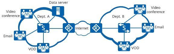
Take enterprise office as an example. In addition to the basic web browsing and email services, services such as Telnet-based device login, remote video conferences, real-time voice calls, FTP file upload and download, and video playback must also have their network quality guaranteed during busy hours. If services have varying network quality requirements, you can configure corresponding QoS functions or enable QoS only for some services to meet the requirements.

qos

  • Network protocols and management protocols: such as OSPF and Telnet

    These services require low delay and low packet loss rate, but do not require high bandwidth. To meet the requirements of such services, configure priority mapping to map the priority of the service packets into a higher CoS value so that the network device can preferentially forward the packets.

  • Real-time services: such as video conference and VoIP

    Video conferences require high bandwidth, low delay, and low jitter. To meet the requirements of such services, configure traffic policing to provide high bandwidth for video packets and priority mapping to increase the priority of video packets.

    VoIP refers to the real-time voice call over the IP network. It requires low packet loss, delay, and jitter. If these requirements cannot be met, both parties of a call will suffer from poor call quality. To resolve this problem, configure priority mapping so that voice packets take precedence over video packets and configure traffic policing to provide the maximum bandwidth for voice packets. This ensures that voice packets are preferentially forwarded in the case of network congestion.

  • Heavy-traffic services: such as FTP, database backup, and file dump

    Heavy-traffic services refer to network services in which a large amount of data is transmitted for a long time. Such services require a low packet loss rate. To meet the requirements of such services, configure traffic shaping to cache the service packets sent from an interface in the data buffer. This reduces packet loss upon congestion caused by burst traffic.

  • Streaming media: such as online audio playback and video on demand (VOD)

    Users can cache audio and video programs before playing them, reducing requirements on the network delay, packet loss, and jitter. To reduce the packet loss rate and delay of these services, configure priority mapping to increase the priority of the service packets.

  • Common services: such as HTML web page browsing and email

    Common services have no special requirements on the network. You do not need to deploy QoS for them.

Service Models

How are QoS indicators defined within proper ranges to improve network service quality? The answer lies in the QoS model. QoS is an overall solution, instead of being merely a single function. When two hosts on a network communicate with each other, traffic between them may traverse a large number of devices. QoS can guarantee E2E service quality only when all devices on the network use a unified QoS service model.

The following describes the three mainstream QoS models. Huawei switches, routers, firewalls, and WLAN devices support QoS based on Differentiated Services (DiffServ), which is the most commonly used.

Best-Effort

Best-Effort is the default service model for the Internet and applies to various network applications, such as FTP and email. It is the simplest service model, in which an application can send any number of packets at any time without notifying the network. The network then makes the best effort to transmit the packets but provides no guarantee of performance in terms of delay and reliability. The Best-Effort model is suitable for services that have low requirements for delay and packet loss rate.

Integrated Service (IntServ)

In the IntServ model, an application uses a signaling protocol to notify the network of its traffic parameters and apply for a specific level of QoS before sending packets. The network reserves resources for the application based on the traffic parameters. After the application receives an acknowledgement message and confirms that sufficient resources have been reserved, it starts to send packets within the range specified by the traffic parameters. The network maintains a state for each packet flow and performs QoS behaviors based on this state to guarantee application performance.

The IntServ model uses Resource Reservation Protocol (RSVP) for signaling. Resources such as bandwidth and priority are reserved on a known path, and each network element along the path must reserve required resources for data flows requiring QoS guarantee. Each network element checks whether sufficient resources can be reserved based on these RSVP messages. The path is available only when all involved network elements can provide sufficient resources.

DiffServ

DiffServ classifies packets on a network into multiple classes and provides differentiated processing for each class. In this way, when congestion occurs, classes with a higher priority are given preference. Packets of the same class are aggregated and sent as a whole to ensure the same delay, jitter, and packet loss rate.

In the DiffServ model, traffic classification and aggregation are completed on border nodes. A border node flexibly classifies packets based on a combination of different fields (such as the source and destination addresses, priority in the ToS field, and protocol type), and marks different classes of packets with appropriate priority values. Other nodes only need to identify these markings to allocate resources and control traffic.

Unlike the IntServ model, the DiffServ model does not require a signaling protocol. In this model, an application does not need to apply for network resources before sending packets. Instead, the application sets QoS parameters in the packets, through which the network can learn the QoS requirements of the application. The network provides differentiated services based on the QoS parameters of each data flow and does not need to maintain a state for each data flow. DiffServ takes full advantage of IP networks' flexibility and extensibility and transforms information in packets into per-hop behaviors (PHBs), greatly reducing signaling operations.

Mechanisms in the DiffServ Model

The DiffServ model involves the following QoS mechanisms:

  • Traffic classification and marking

    Traffic classification and marking are prerequisites for implementing differentiated services. Traffic classification divides packets into different classes, and can be implemented using traffic classifiers configured using Modular QoS Command-Line Interface (MQC). Traffic marking sets different priorities for packets and can be implemented through priority mapping and re-marking. Packets carry different types of precedence field depending on the network type. For example, packets carry the 802.1p field in a VLAN network, the EXP field on an MPLS network, and the DSCP field on an IP network.

  • Traffic policing, traffic shaping, and interface-based rate limiting

    Traffic policing and traffic shaping control the traffic rate within a bandwidth limit. Traffic policing drops excess traffic when the traffic rate exceeds the limit, whereas traffic shaping buffers excess traffic. Traffic policing and traffic shaping can be performed on an interface to implement interface-based rate limiting.

  • Congestion management and congestion avoidance

    Congestion management buffers packets in queues upon network congestion and determines the forwarding order using a specific scheduling algorithm. Congestion avoidance monitors network resource usage and drops packets to mitigate network overloading when congestion worsens.

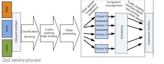
Traffic classification and marking are the basis of differentiated services. Traffic policing, traffic shaping, interface-based rate limiting, congestion management, and congestion avoidance control network traffic and resource allocation to implement differentiated services.

The following figure shows the QoS service process on network devices.

qs

QoS vs. HQoS

Traditional QoS technologies can provide differentiated services to meet requirements of voice, video, and data services. As the number of users and their individual bandwidth consumptions continue to grow, these technologies are facing new problems, including:
  • Traffic is scheduled based on interface bandwidth, allowing differentiation of traffic based on service levels. However, it is difficult to differentiate services based on users. Therefore, traditional QoS is typically applied to the core layer, instead of the access layer.

  • Traditional QoS cannot manage or schedule traffic of multiple services for multiple users simultaneously.

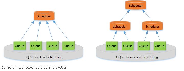
Hierarchical Quality of Service (HQoS) has been introduced to address these issues by differentiating traffic of different users and scheduling traffic based on service priorities. HQoS uses multiple levels of queues to further differentiate service traffic, and provides uniform management and hierarchical scheduling for transmission objects such as users and services. It enables network devices to control internal resources, providing QoS guarantee for VIP users while reducing network construction costs.

q

Thursday, September 8, 2022

Introduction to Portal Authentication

802.1X and PPPoE access control methods require dedicated client software to be installed and are effective only at the access layer, which does not facilitate network deployment and user access. To solve this problem, an access control mode, which does not require dedicated client software and allows authentication control points to be flexibly deployed, is required.

Portal authentication is developed in this context. It does not require dedicated clients, providing a flexible access control mode. Access control can be implemented at the access layer and the ingress of key data to be protected. Portal authentication is also called web authentication because it uses popular web pages for authentication, which means that users can be authenticated using only a web browser.

MAC address-prioritized portal authentication can be used to avoid frequent password and account entry for reauthentication in the case that a user roams or goes offline and then online again in various scenarios.

In MAC address-prioritized portal authentication, the access device sends the MAC address of a terminal to the RADIUS server for authentication when the terminal performs portal authentication for the first time. If the authentication fails, portal authentication is triggered for the user so that the user can enter the user name and password for identity authentication. The RADIUS server caches a terminal user's MAC address after the first authentication succeeds. If the terminal user is disconnected and then connected to the network within the MAC address validity period, the RADIUS server searches for the MAC address of the terminal user in the cache to authenticate the terminal user. After the authentication succeeds, the portal authentication page is not pushed to the user, and the user can directly access network resources.

  • Portal authentication takes effect based on physical ports. If a user connected to a port passes the authentication, the user can access network resources through the port. If a user fails to pass the authentication, the user cannot access network resources.
  • Currently, ports that are enabled with portal authentication support only network resource access through HTTP, and does not support other services (such as connected printers, IPC services, AP services, and dumb terminals). If other services need to be supported, use other ports for service isolation.
  • Currently, only the portal protocol 2.0 is supported.

HTTP has security risks due to its limitations. Ensure that HTTP is used in a secure environment.

A portal authentication system consists of authentication clients, access device Huawei MA5800 OLT or MA5600T GPON OLT, portal server, and RADIUS server. The portal server and RADIUS server are built in iMaster NCE-Campus, as shown in Figure 1.

Figure 1 Portal authentication system


  • Authentication client: A browser that runs the HTTP protocol or a host that runs the portal client software.
  • Access device (OLT Huawei MA5800 X7 for example):
    • Redirects all HTTP requests of a user to the portal server before authentication.
    • Interacts with the portal server and RADIUS server to implement identity authentication.
    • Allows the user to access authorized network resources after the authentication succeeds.
  • Portal server: Receives authentication requests from a portal client, provides portal services and authentication web pages, and exchanges authentication information of the authentication client with the access device.
  • RADIUS server: Interacts with the access device to authenticate users.

Tuesday, August 16, 2022

How do I prevent rogue devices from connecting to my Huawei ONT's Wi-Fi?

Huawei EchoLife ONT include HG8010, HG8010H, HG8045, HG8045A, HG8240, HG8240H, HG8240T, HG8240W, HG8245, HG8245H, HG8245Q, HG8245T, HG8247, HG8247H, and router etc.

HG8010, HG8010H, HG8240, HG8240H, HG8240T, HG8240W are bridging ONTs and do not have the Wi-Fi function.You need to perform on the connected router, consult the router vendor or the carrier service hotline.

For Huawei ONTs with Wi-Fi functions, such as HG8045, HG8045A, HG8245, HG8245H, HG8245Q, HG8245T, HG8247 and HG8247H, perform the following steps:

  1. Exercise caution when using software to access Wi-Fi without permission. Such software uploads a user's Wi-Fi network information without notification. Another user can find this Wi-Fi network name, obtain the Wi-Fi network key from the software server through a 3G or 4G network, and access this Wi-Fi network without permission.
  2. Check whether encryption has been performed for the Wi-Fi network. Specifically, log in to the ONT web page. On the main menu, choose WLAN > 2.4G/5G Basic Network Settings. In WPA PreSharedKey , do not select Hide. .
  3. Check whether the Wi-Fi password is too simple to be cracked. You are advised to set Authentication Mode to WPA-PSK/WPA2-PSK. Configure and record a password with high security level, for example, a password containing digits, uppercase letters, lowercase letters, and special characters. This prevents password cracking.

    The following figure shows the details.


  4. By configuring MAC address filtering, you can allow only permitted devices (whitelist) to access the network, and prevent rogue devices (blacklist) from accessing the network.

Note: For some ONTs, you can configure a Wi-Fi password after choosing Advanced Configuration > WLAN > 2.4G/5G Basic Network Settings. on the ONT web page.

Tuesday, July 19, 2022

Huawei ONU S800E-M cannot get UP in Huawei MA5800 OLT

Issue Description

Customer is using the device S800E-M to connect to OLT, but ONT cannot get online into OLT MA5800 X2 V100R019C20, next message  appears:


Handling Process


1- The OptiXstar S800E is a miniature XGS-PON SFP ONU device that can be inserted into the SFP port of a camera or AP device to provide XGS-PON access for the device to meet the requirements of video backhaul or wireless backhaul.


So we checked the compatibility between this device and OLT model and they are compatibles.


2- Checked the status on NCE:


3- Also it was checked the configuration in OLT, it was fine because the ont-auto-find was  enabled and ONT add correctly.

4- Then it was perfomed a test in our lab, collected logs from device customer and lab environment to compare them.

on the lab it worked fine as Normal:


Customer logs with issue:


Root Cause

Condition: The system contains the xPON app patch. The rollback is canceled.
Symptom: After the device is powered off or reset unexpectedly and switches to the backup area, the xPON app patch is lost.
Impact: Functions of the xPON app patch are lost.
 

Solution

Upgrade OLT to version R20C10SPH308, or later.

Monday, June 27, 2022

Troubleshooting of GPON ONU Profile Match state is Mismatch

GPON ONU Profile Match state is Mismatch

An Huawei GPON ONU connected to a GPON port of an Huawei MA5800 OLT or MA5600T OLT can go online successfully, but the queried Match state of the ONU is displayed as mismatch by running the display ont info command on the OLT.

Context

The ONU matching status indicates whether the actual ONU capability is the same as the service profile bound to the ONU. The status includes: initial, mismatch, and match. To some extent, the matching status is determined by the ONU running status and configuration status.

  • The matching status of the ONU can be queried only when the ONU running status is online. The matching status is match when the actual hardware capability of ONU is the same as the ONU service profile bound with the ONU. Otherwise, the status is mismatch.
  • In other configuration states, the matching status is initial.
  • The ONU matching status does not affect the normal forwarding of the service flow, and only indicates whether the actual ONU capability is the same as the service profile bound to the ONU.
In practice, ONUs in the offline state are bulk pre-configured on the OLT to facilitate service provisioning. An ONU service profile and an ONU line profile are specified during such configurations. The ONU profiles together can be regarded as a virtual ONU. Subsequent services are configured based on this virtual ONU. Inconsistency between the capability set configured in the ONU profiles and the actual ONU capabilities involves the following two situations:
  • The configured capability set outmatches the actual ONU capabilities. If the ONU is bound to such ONU profiles, ONU configurations will fail to match when the ONU goes online.
  • The configured capability set undermatches the actual ONU capabilities. In this case, the ONU capabilities that are not covered by the ONU profiles will fail to be configured or applied.

Location Method

When the queried Match state of the ONU is displayed as mismatch, locate the fault according to the following procedure:
  1. Check whether the capability set configured in the ONU service profile matches the actual ONU capabilities.

Procedure

  1. Run the display ont capability command to query the actual ONU capabilities. According to the data plan, modify the current ONU profiles, or bind matching ONU profiles to the ONU.

    • If this problem occurs on all the ONUs of the same type, the configurations of the ONU profiles may be incorrect.
      • If the OLT works in the distributed mode, the profiles that are bound to the ONU cannot be modified or deleted. In this case, bind matching ONU profiles to the ONU.
      • If the OLT works in the profile mode:
        1. Run the display ont-srvprofile command to query the information about the ONU service profile and run the display ont-lineprofile command to query the information about the ONU line profile.
        2. Modify the ONU profiles by referring to Configuring a GPON ONT Profile in the Commissioning and Configuration Guide.
    • If this problem occurs on only one ONU, it is suggested to bind matching ONU profiles to the ONU.
      • If the OLT works in the distributed mode:
        1. Run the display ont-profile command to query the current ONU profiles that are configured on the OLT.
        2. If the OLT does not have matching ONU profiles, run the ont-profile add command to add matching ONU profiles.
        3. Run the ont modify command to bind the ONU profiles to the ONU.
      • If the OLT works in the profile mode:
        1. Run the display ont-srvprofile command to query the information about the ONU service profile and run the display ont-lineprofile command to query the information about the ONU line profile.
        2. If the OLT does not have matching ONU profiles, add matching ONU profiles by referring to Configuring a GPON ONT Profile in the Commissioning and Configuration Guide.
        3. In the GPON mode of the OLT, run the ont modify command to bind the ONU profiles to the ONU.

  2. Check whether Match state of the ONU is displayed as match.
    • If Match state of the ONU is displayed as match, go to 4.
    • If Match state of the ONU is displayed as mismatch, proceed to 3.
  3. Connect Thunder-link.com for technical support.
  4. The fault is rectified.

Sunday, June 12, 2022

Why ICMP delay with jumbo frames between Huawei and Cisco switch?

This case mainly talks about the ICMP delay caused by the packet processing mechanism of the CE switch.

Problem Description

The CE12808 switch is connected to the CRS_Router Cisco switch through four Layer 3 interfaces. After the interconnection, it's found that the ICMP delay between the two devices is long.


imgDownload?uuid=bd70c794892a43068942105


To check whether the link is normal, we make an ICMP test with large Packets and see the following on Huawei & Cisco.


1. From Huawei to Cisco :

~Huawei]ping -m 30 -t 8000 -c 100 -s 9152 -a  192.168.23.2 -f  192.168.23.1 

  PING 192.168.23.1: 9152  data bytes, press CTRL_C to break

    Reply from 192.168.23.1: bytes=9152 Sequence=1 ttl=255 time=5 ms

    Reply from 192.168.23.1: bytes=9152 Sequence=2 ttl=255 time=6 ms

    Reply from 192.168.23.1: bytes=9152 Sequence=3 ttl=255 time=3 ms

    Reply from 192.168.23.1: bytes=9152 Sequence=4 ttl=255 time=3 ms

    Reply from 192.168.23.1: bytes=9152 Sequence=9 ttl=255 time=17 ms

    Reply from 192.168.23.1: bytes=9152 Sequence=10 ttl=255 time=59 ms

    Reply from 192.168.23.1: bytes=9152 Sequence=11 ttl=255 time=93 ms

    Reply from 192.168.23.1: bytes=9152 Sequence=12 ttl=255 time=93 ms

    Reply from 192.168.23.1: bytes=9152 Sequence=13 ttl=255 time=93 ms

    Reply from 192.168.23.1: bytes=9152 Sequence=14 ttl=255 time=92 ms

    Reply from 192.168.23.1: bytes=9152 Sequence=15 ttl=255 time=93 ms

                                      ...

    Reply from 192.168.23.1: bytes=9152 Sequence=24 ttl=255 time=92 ms

    Reply from 192.168.23.1: bytes=9152 Sequence=25 ttl=255 time=93 ms


  --- 192.168.23.1 ping statistics ---

    100 packet(s) transmitted

    100 packet(s) received

    0.00% packet loss

    round-trip min/avg/max = 3/84/94 ms


2. From Cisco to Huawei :


Cisco# ping   192.168.24.2 source   192.168.24.1 size 9180 donotfrag count 30000 interval 5


Fri Jul  1 03:50:57.844 GMT


Type escape sequence to abort.


Sending 30000, 9180-byte ICMP Echos to 192.168.24.2, timeout is 2 seconds:


Success rate is 100 percent (153/153), round-trip min/avg/max = 1/90/94 ms


There seems to be some ISSUE on the link interconnect because the delay should not exceed 15 or 20 ms.

Handling Process

Before checking the issue we need to be clear about MTU for Cisco & Huawei:

A. Cisco Interface MTU is 9194: The ICMP test packet length is 9180 bytes through Cisco CRS Ios XR not consider 14 bytes for Ethernet on ICMP Test.

B. Huawei Interface MTU is 9180: The ICMP test packet length is 9152 bytes through  Huawei does not consider 14 bytes for Ethernet, 8 bytes for ICMP, and 6 bytes for VLAN.

1. At the beginning of the issue, we thought the issue was on Optical Fibers and GE 10G Transceivers, so our plan was to verify physical links and made physical loops for verifying the Transceiver. After this, the issue continues.

[~Huawei]display interface 10GE8/0/46  transceiver  verbose  | in DBm

   Current RX Power (dBm)                :-2.79

   Default RX Power High Threshold (dBm) :2.50

   Default RX Power Low Threshold (dBm)  :-16.40

   Current TX Power (dBm)                :-3.75

   Default TX Power High Threshold (dBm) :2.50

   Default TX Power Low Threshold (dBm)  :-10.20

Cisco Ten 0/4/0/0 <<>> Huawei 10GE5/0/46

Cisco#sh controllers tenGigE 0/4/0/0 phy  | in dBm

Fri Jul  1 03:18:00.095 GMT

                Tx power: -3 dBm (4307 in units of 0.1 uW)

                Rx power: -5 dBm (2597 in units of 0.1 uW)


<Huawei>display  interface 10GE5/0/46  transceiver verbose  | in dBm

   Current RX Power (dBm)                :-3.90

   Default RX Power High Threshold (dBm) :2.50

   Default RX Power Low Threshold (dBm)  :-16.40

   Current TX Power (dBm)                :-3.26

   Default TX Power High Threshold (dBm) :2.50

   Default TX Power Low Threshold (dBm)  :-10.20


2. Verify the packets for ICMP statistics and check if there is some issue with processing :


<Huawei>disp current-configuration configuration include-default | i fast

undo arp fast-reply disable

undo icmp echo-reply fast disable


[~Huawei]display icmp fast-reply statistics slot 5

------------------------ Display ICMP Statistics -------------------------------

Received packets:                                                              

     request packets:                             0                            

     invalid request packets:                     0                            

     failed to get vrf:                           0                            

     destination is not host ip:                  0                            

     failed to get ctrl word:                     0                            

Send packets:                                                                   

     successful reply packets:                    0                            

     failed reply packets:                        0                            


[~Huawei]display icmp fast-reply statistics slot 8

------------------------ Display ICMP Statistics -------------------------------

Received packets:                                                               

     request packets:                             0                            

     invalid request packets:                     0                            

     failed to get vrf:                           0                            

     destination is not host ip:                  0                            

     failed to get ctrl word:                     0                            

Send packets:                                                                  

     successful reply packets:                    0                            

     failed reply packets:                        0                            


[~Huawei]display icmp fast-reply statistics slot 1


------------------------ Display ICMP Statistics -------------------------------

Received packets:                                                              

     request packets:                             0                             

     invalid request packets:                     0                            

     failed to get vrf:                           0                            

     destination is not host ip:                  0                             

     failed to get ctrl word:                     0                            

Send packets:                                                                  

     successful reply packets:                    0                            

     failed reply packets:                        0                            

--------------------------------------------------------------------------------


[~Huawei]display icmp fast-reply statistics slot 4

------------------------ Display ICMP Statistics -------------------------------

Received packets:                                                              

     request packets:                             0                            

     invalid request packets:                     0                            

     failed to get vrf:                           0                            

     destination is not host ip:                  0                            

     failed to get ctrl word:                     0                             

Send packets:                                                                  

     successful reply packets:                    0                            

     failed reply packets:                        0                            

--------------------------------------------------------------------------------

Root Cause

The Ping Packet Processing on a CE Switch is like follows :

imgDownload?uuid=218fdfcb05dc45c28d3e53b

1. The green line in the preceding figure shows ping packet processing. The forwarding plane sends ping packets to the control plane through the CPU. The processing latency mainly includes the latency on the forwarding plane and the latency on the control plane. The latency on the forwarding plane is at the microsecond level and can be ignored. The latency on the control plane is determined by the CPU usage. If the CPU usage is high, the latency increases.

2. The red lines show service data flow processing. Service data packets are directly forwarded by the forwarding plane and are not processed by the control plane. The latency is at the microsecond level.

Analysis of Latency and Jitter During Ping Packet Transmission Between CE and Cisco Switches :

Ping packet processing is as follows:

1.  The packet receiving process on the CE switch is as follows:

Control plane of the Cisco switch -> packet sending by the CPU of the Cisco switch -> forwarding plane of the Cisco switch -> forwarding plane of the CE switch -> packet receiving by the CPU of the CE switch -> control plane of the CE switch

2. The packet forwarding process on the CE switch is as follows:

Control plane of the CE switch -> packet sending by the CPU of the CE switch -> forwarding plane of the CE switch -> forwarding plane of the Cisco switch -> packet receiving by the CPU of the Cisco switch -> control plane of the Cisco switch.

Solution

The latency of ping packets mainly includes the processing latency on the Cisco switch and the processing latency on the CE switch. The processing latency on the CE switch mainly includes the latency on the forwarding plane and the latency on the control plane.

The latency on the forwarding plane is at the microsecond level and can be ignored. The latency on the control plane is determined by the CPU usage. If the CPU usage is high, the latency increases.

Because of the CPU performance and software calculation priority of the CE switch, a little latency and jitter may occur for ping packets that need to be processed by the CPU. However, data packet forwarding is not affected on the CE switch because data packets are forwarded by the hardware and software processing is not involved.

Suggestions and Summary

As we mentioned this issue is just related to IMCP Test, not with Traffic of Services.

That's true because when we put traffic on the Internet there is no issue with users.

Before the ICMP test, ensure that the test does not affect service traffic processing.