Tuesday, January 30, 2024

Why we cannot query OSNR from NMS by OPM8 board?

This post is about the issue that Impossible to query OSNR from NMS by Huawei OPM8 board. Do have a look below for more information on the topic.


Issue Description

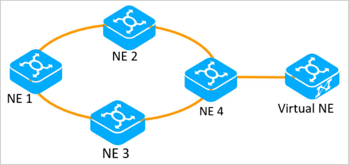
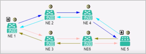
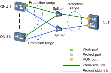
Networking Topology:


205523o2m5tj6vbojby4xv.png


Fault Symptom:

Failed to query OSNR by OPM8 board on site B.


205553chhmh0mmm277ox7o.png

Handling Process

1. In 100G system, the OSNR is calculated by EMCA module in the system control board. Even though, query the OSNR by OPM8 board, but it's not calculated by OPM8 direclty.

2. The EMCA module in the system control board performs modeling for each board and fiber type in an OMS trail. During calculation, the EMCA module obtains the input and output multiplexed-wavelength optical power of each OA on the OMS trail, and the single-wavelength signal and noise power scanned by the OPM8 board to calculate the single-wavelength OSNR.

3. So the OSNR calculation depends on the OMS OD route configuration. 

4. Check the "OD Route Configuration" of the OMS between site A and site B, the status is "Partially Created". Try to create once again by clicking "New", it reported "Not Supported Board Type (Error code: 38664)".


205627vtt7401xj7ua100p.png

5. Check all the boards on the OMS trail, in Site B, there are 15OAU, 52WSMD9, 55OPM8. Those boards can't be supported by Site A(OptiX OSN8800 UPS V100R012C10SPC300).

6. The Site B is new implemented, some new boards are not supported by Site A. So can't create the "OD Route Configuration". Finally, failed to calculate the OSNR.

Root Cause

The Site B is new implemented, some new boards are not supported by Site A. So can't create the "OD Route Configuration". Finally, failed to calculate the OSNR.


Solution

1. Upgrade Site A to R13C10SPC700 or later version, so Site A can support 15OAU, 52WSMD9, 55OPM8.

2. Create the 15OAU, 52WSMD9, 55OPM8 as logic board with the lower version, so Site A can support.


Suggestions

1. The OSNR of 100G system is calculated by EMCA module in the system control board, it depend on the OMS and "OD Route Configuration".

2. In the implementation phase, should consider the board can be supported, not only the current device, also should be supported by the peer device of OMS. 

How to convert between common E1 services and E1 SNCP services?

This post will share how to convert between common E1 services and E1 SNCP services. 

Scenario Description

The network topology consists of four OptiX OSN 3500 and one virtual NE.


SDH


Carries two common E1 services.


SDH


Video

This video will show how to convert between common E1 services and E1 SNCP services, and how to implement conversion on virtual NEs after topology changes.


Text description


Converting common E1 services to E1 SNCP services

1. Confirm the existing E1 services.

2. Configure dual-fed and selective receiving on NE1.

A. Expanding bidirectional services into unidirectional services

B. Convert the unidirectional service whose signal source is a line board and whose signal sink is a tributary board to an SNCP service. The two services need to be configured separately.

C. Create the unidirectional service in the reverse direction by referring to the generated protection service. The two services can be configured at the same time.

3. Configure two bidirectional pass-throughs on NE3.

4. Configure the dual-fed and selective receiving service on NE4.

A. Expand bidirectional services as unidirectional services.

B. For the services forwarded to the virtual NE, convert the unidirectional services whose signal source is a dual-fed line board and whose signal sink is a selective-receiving line board into SNCP services. For the services dropped locally, select the unidirectional service whose signal source is a line board and the signal sink is a tributary board to convert the services to SNCP services.

C. Configure unidirectional services in the reverse direction according to the generated protection services.

5. Search for new SDH trails. 

Searching for new SDH trails = Refreshing SDH trails

Results:


SDH


Please note:

1. On NE1 and NE4, the signal source is dual-transmit end and the signal sink is selective receive end, and the unidirectional service is converted into SNCP services. If the selection is incorrect, the conversion fails.

2. During the configuration, the timeslots occupied by the E1 services in each place must be correct. Otherwise, E1 SNCP trails cannot be searched out in the last step.


Converting E1 SNCP services to common E1 services

1. Operations on NE1

A. Expand a bidirectional path into a unidirectional path.

B. Restore the SNCP service to an unprotected service. When you select a unidirectional working service, the protection service is automatically selected.

Another simpler method is to select the protection service between, right-click, and choose Convert to Non-Protection Service from the shortcut menu. This does not require step A.


SDH


C. Delete unnecessary unidirectional services.


2. Delete the pass-through service from NE3.


3. On NE4, convert the SNCP service to the non-protection service. The operation method is the same as that of step 1.


4. Search for SDH trails again.


Service conversion on virtual NE

After NE6 is added to the topology, the virtual NE service can be used as the node of the SNCP service. Therefore, the first E1 service can be converted again. When two SNCP nodes are at both ends of an E1 path, the protection capability is the best.

1. Configure services on NE1, NE3, and NE6.

The configuration method is the same as above.


2. Configure SNCP services for virtual NEs.

Common E1 services cannot be converted to SNCP E1 services on virtual NEs.

Solution:

A. In the NE Explorer of the virtual NE, delete the original E1 service,

B. Create an SNCP service. The working timeslot must be the same as the deleted timeslot.

After the configuration is complete, the unidirectional service in the reverse direction is automatically created. It no needs to manually create the service again.


3. Search for SDH trails again.

Results:


SDH


Please note:

1. When converting an E1 SNCP service to a common E1 service, it needs to delete the entire E1 SNCP service on the virtual NE and then create the common E1 service.

2. Creating, deleting, or modifying services on virtual NEs does not affect services.

Wednesday, January 3, 2024

E224 not Working with BD_fILE_NOT_Active Alarm

 Description

A new 1G ethernet port in TNV3E224 installed in OSN 9800 U32E didn’t work after being configured and show no traffic in the transmit or receive direction.


no traffic

Procedures of Check 

The first thing is checking the optical power and after checking, I found that the optical power is in the optimal range.

power is ok


After that I wanted to confirm whether the port has configured services or not, so there should be a traffic in it, and it was already configured with several PWs in a correct way.

Then I come to check alarms and found that there is a Major Alarm in the board named (BD_fILE_NOT_Active ).


alarm

From the alarm details, the parameters of the alarm are 0x03 0x00 0x03 

parameter.

The Solution

referring to the NCE help with the alarm parameters, the causes are a file missed.

The details of this file are as follow:-

  • 0x01: board software (BDSOFT).
  • 0x03: control logic (FPGA).
  • 0x04: CPLD.
  • 0x05: configuration file (ne.ini).
  • 0x07: service logic 1 (FPGA).
  • 0x08: service logic 2 (FPGA).
  • 0x09: service logic 3 (FPGA).

As the parameter was 0X03 so the FPGA is the missed file, the possible cause is that, The logic or CPLD in the file system where the board is located is updated during package loading. The CPLD or FPGA file of the board can be activated only after the board undergoes a cold reset or power failure. This alarm is reported when the CPLD or FPGA file of the board is not activated.


As explained the board needs a cold reset or unplug then plug it, to activate the FPGA file after a software update, and after I made a cold reset for it, the alarm cleared and the board worked normally.


Note:-Usually boards bought long time before deployment need a upgrade for the soft, and if not follow all the procedures of the upgrade a total or partial failure happens to the board.


Tuesday, January 2, 2024

Introduction to xPON Type C Protection

Introduction to xPON Type C Protection

Type C provides redundancy for OLT (dual homing), ONU's PON ports, backbone fibers, optical splitters, and distribution optical fibers. When a fault occurs, services can be automatically switched to the functional link. After the fault is rectified, services are automatically switched back to the original link.

xPON type C protection can be deployed in two networking scenarios: single homing and dual homing.

Figure 1 shows the xPON type C protection single homing network.

Figure 1 xPON type C protection network (single homing)
SINGLE

Networking Mode

Advantage

Disadvantage

Scenario

Single homing

The networking mode is simple, and OLT and ONU can be managed easily.

When the OLT becomes faulty, services are interrupted. Optical fibers are deployed on the same channel and therefore two optical fibers may be broken at the same time.

This mode is used to protect important services, such as Enterprise private line services and base station services.


Figure 2 shows the xPON type C protection dual homing network.

Figure 2 xPON type C protection network (dual homing)
DUAL
 

Networking Mode

Advantage

Disadvantage

Scenario

Dual homing

When the active OLT or its uplink fails, services can be switched to the standby OLT.

The networking mode is complicated and costly, and the ONU management is difficult.

This mode is used to protect a power system or Enterprise private line services and base station services.


On a single homing network, one ONU such as Huawei MA5626 is connected to two PON ports on an OLT, one working as the active port and the other as standby. The two ports on the OLT cannot forward packets at the same time. An automatic switching can be triggered by any of the following conditions:

  • Loss of signal (LOS) occurs in the input direction.
  • The ONU is offline.
  • The OLT or ONU hardware is faulty.


On a dual homing network, two PON lines, one working as the active line and one as standby, between an ONU and two OLTs cannot forward packets at the same time. An automatic switchover can be triggered by any of the following conditions:

  • Loss of signal (LOS) occurs in the input direction.
  • The ONU is offline.
  • The OLT or ONU hardware is faulty.
  • The OLT's uplink is faulty (this condition triggers automatic switching only in the associated protection switching scenario).


If you want to know more information about xPON type C protection, you can contact Thunder-link.com.

Tuesday, November 28, 2023

Why the patch can’t be activated on CE12808?

Issue Description

Can’t activated the patch on CE12808


< -ce12808- >patch load flash:/CE12800-V200R019SPH060.PAT all active

Info: Operating, please wait for a moment.......

Error: The service pack version does not match the system software version.

< -ce12808- >check patch flash:/CE12800-V200R019SPH060.PAT

Warning: Patch package verification consumes system CPU resources. Continue? [Y/N]:y

Info: Prepare to check patch file flash:/CE12800-V200R019SPH060.PAT, please wait....done.

Info: Digital signature verification of the system patch succeeded.


Handling Process

  1. Checked the software version V200R019C00SPC800


  1. When we checked this version, we found it end of support  version


  1. Also when we checked on the system no any patches are available for this end of support version V200R019C00only available versions for V200R019C10.


  1. The patch that you are trying to upload V200R019SPH060, it’s patch for V200R019C10, not for the current version which is running on the switch V200R019C00
  2. That’s why you observed the below error when trying to install the patch

Error: The service pack version does not match the system software version


Root Cause

installing incorrect patch

Solution

The current running software version is end of support, no any available patches for this version.

 advised to upgrade the version and patch to the recommended one. 

Thursday, November 9, 2023

How to Identify Huawei-Certified Switch Optical Modules

  • A switch must use optical or copper modules that have been certified for use on Huawei S switches. Non-certified optical or copper modules cannot ensure transmission reliability and may affect service stability. Huawei is not liable for any problem caused by the use of non-certified optical or copper modules and will not fix such problems.

  • The methods provided here are only for reference. To confirm whether optical modules you are using have been certified for use on Huawei S switches, contact Huawei technical support.

10GE or Lower Speed Optical Modules

Huawei started certification on 10GE or lower speed optical modules for S switch products on July 1, 2013.

To determine whether optical modules delivered for Huawei S switches before July 1, 2013 are certified ones, contact Huawei technical support.

If your optical modules are delivered after July 1, 2013, use either of the following methods to determine whether they have been certified by Huawei.

Method 1: Check for "HUAWEI" on the label

If an optical module has been certified by Huawei, its label contains "HUAWEI", as shown in Figure 10-1.

Figure 10-1 "HUAWEI" on the label of a Huawei-certified S switch optical module

Method 2: Run the command

An optical module has received Huawei S switch certification if it meets the following conditions:

For a device running V200 version:

  • In the display elabel command output, the Manufactured field displays a date later than 2013-07-01.

  • In the display version command output, the displayed version is V200R001C00 or later.

  • In the display transceiver command output, the Vendor Name field displays HUAWEI.

The SFP-FE-SX-MM1310 (part number: 02315233) is a Huawei-certified 100M optical module. However, the Vendor Name field displays the original manufacturer name, instead of HUAWEI.

For copper modules, the Vendor Name field also displays the original manufacturer name, instead of HUAWEI.

25GE, 40GE, and 100GE QSFP28 Optical Modules

Huawei started certification on 25GE, 40GE, and 100GE optical modules for S switch products on January 1, 2016.

To determine whether optical modules delivered for Huawei S switches before January 1, 2016 are certified ones, contact Huawei technical support.

If your optical modules are delivered after January 1, 2016, use either of the following methods to determine whether they have been certified by Huawei.

Method 1: Check for "HUAWEI" on the label

If an optical module has been certified by Huawei, its label contains "HUAWEI", as shown in Figure 10-1.

Method 2: Run the command

A 25GE, 40GE, or 100GE optical module has received Huawei S switch certification if it meets the following conditions:

For a device running V200 version:

  • In the display elabel command output, the Manufactured field displays a date later than 2016-01-01.

  • In the display version command output, the displayed version is V200R008 or later.

  • In the display transceiver command output, the Vendor Name field displays HUAWEI.

For the optical modules connected to high-speed cables or AOC cables, the Vendor Name field displays the original manufacturer name, instead of HUAWEI. For the methods of checking whether such an optical module has been certified by Huawei, contact Huawei technical support personnel.