Thursday, April 29, 2021

How to checking the Temperature of Each Board on Huawei Router?

 This section describes how to verify Huawei router like NE40E ME60-X8 boards temperature

Prerequisites

The router has been logged in to.

Procedure

  1. Run the display temperature[ [ lpu | mpu | sfu ] slot slot-id [ pic pic-id ] ] command to view the temperature status on each board

    <HUAWEI> display temperature
    SlotID2
     Base-Board, Unit:C, Slot2
    PCB   I2C Addr Chl  Status  Minor Major Fatal Adj_speed Temp
                                                  TMin Tmax (C)
    -----------------------------------------------------------------
    LPUF  1   1    0    NORMAL  70    80    90    60   70   36
    LPUF  1   2    0    NORMAL  60    70    80    50   60   33
    LPUF  1   4    0    NORMAL  70    80    90    60   70   35
    LPUF  1   5    0    NORMAL  80    90    100   70   80   39
    LPUF  1   6    0    NORMAL  70    80    90    60   70   38
    LPUF  2   76   1    NORMAL  90    96    102   80   90   39
    LPUF  2   76   2    NORMAL  90    96    102   80   90   40
    TCMB  1   3    0    NORMAL  70    80    90    60   70   34
    TCMB  1   7    0    NORMAL  60    70    80    50   60   31

    Pay attention to the values of boldfaced fields displayed. The Temp(C) field indicates the current temperature. The Minor field indicates the threshold of a high temperature for a minor alarm. The Major field indicates the threshold of a high temperature for a major alarm. The Fatal field indicates the threshold of a high temperature for a critical alarm. If the board temperature reaches or exceeds the value of the Fatal field, Huawe ME60 may work abnormally or be damaged.

    If the displayed value of the Temp(C) field is lower than that of the Minor field, the board temperature is normal. Then, go on with the subsequent commissioning.

Troubleshooting

If the board temperature exceeds the threshold, perform the following operations:

  1. Check whether fans are faulty and replace any faulty fans.

  2. Check whether the air filter is clogged. If it is clogged, clean it.

  3. Check whether the ambient temperature is too high. If the ambient temperature is too high, lower the temperature in the equipment room.

  4. If the board temperature is still high after the preceding operations, it is due to the high chip temperature. In this case, no action is required or contact Huawei technical support personnel.

Thursday, April 15, 2021

What are the BGP VPNv4 and Labeled BGP routes?

During the studying of MPLS VPN, we usually encounter the VPNv4 and Labeled BGP routes of Huawei switch and Router. A lot of people can't distinguish between them. Actually, they are so different from each other.


Before talking about the VPNv4 and the Labeled BFP routes, let's check the normal BGP route:


normal_bgp

The VPNv4 route


The VPNv4 route is comprised of two parts: the IPv4 route and the route-distinguisher. The route-distinguisher is used to distinguish the different VPN-instances. The router can forward the VPNv4 route to the appropriate VPN-instance. When the BGP updates the VPNv4 route, the RD (route-distinguisher) will be contained in the MP_REACH_NLRI field, just as the picture below shows. 


vpnv4

We noticed that a route-target value was attached in the EXTENDED_COMMUNITIES field. The route-target is used by the VPN-instance to decide whether the VPNv4 route will be accepted.


Labeled BGP route


Unlike the VPNv4 route, the Labeled BGP route is more similar to the normal BGP route. But the Labeled BGP route and the normal BGP route are also quite different.


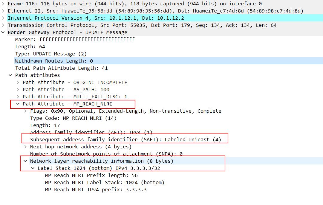
In the Labeled BGP route, a MP_REACH_NLRI is attached as a VPNv4 BGP route does, but unlike the VPNv4 route, there is no RD or RT (route-target). It only carries a label stack, and the normal BGP route doesn't, just showing as the picture below:

label-BGP-route

The Labeled BGP route is used in MPLS VPN option C. Between the two ASBR, the labeled BGP route is transferred so that the label distributed by the different VPN-instances could pass through the different AS.


Friday, March 19, 2021

How do you Make Hardware and Software Loopback for OSN1800?

 How do you Make Hardware and Software Loopback for OSN1800?

The Loopback means of troubleshooting for Equipment and used to determine whether the boards, Optical interface, Electrical interface, Cables, Connectors and Cross-Connection are faulty

A.      OTU Board Loopback

B.      OTN Tributary Board Loopback

C.      OTN Line Board Loopback

D.     SDH Board Loopback

E.      PDH Board Loopback

F.       Ethernet Board Loopback

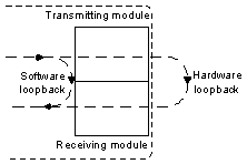
Hardware Loopback: Means an optical port connect the transmit end and receive end of the Port using a fiber and it must be performed onsite

Software Loopback: Means configure the Loop on the NMS
1

A-   OTU Board Loopback: A loopback is used to determine whether the board is faultyTypes of loopback which we can apply them on The OTU boards to verify the board SDH services as the following

1-  Client –Side Out-loop  : this loop is used to detect whether the Fiber line and Connectors on the line are normal as the Following
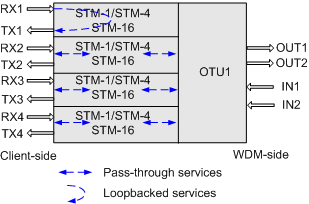

2


2-  Client –Side In-loop  : The loop is used to detect whether the received Signals are properly processed inside the board as the following 
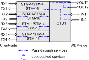
 

3


3-   WDM –Side In-loop  : this loop is used to detect whether the received Signals are properly processed inside the board as the following 
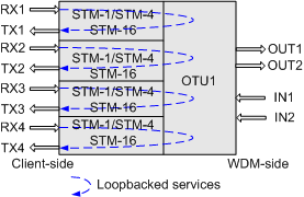
 

4


4-  WDM –Side out-loop  : The loop is used to detect whether the Fiber line and Connectors on the line are normal as the following 
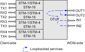
 

5


B- OTN Tributary Board Loopback: An OTN tributary board we can do Inloop and Outloop to determine which Fault. The types of Loops as the following:

1-  Out-loop on the OTN Tributary Board  : this loop is used to Check whether optical Fibers and Connectors Functions properly  as the following 
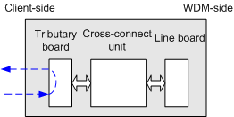
6


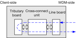
2-    In-loop on the OTN Tributary Board  : this loop is used to Check whether the board Properly processes received Signals as follows
7


 C-OTN Line Board LoopbackAn OTN line board which include In-Loop and Out-loop

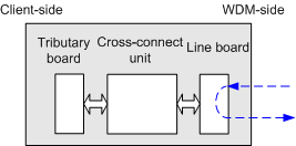
1-  Out- loop on an OTN Line Board  : this loop is used to Check Fibers line and Connectors Function are Working Properly as follows
8


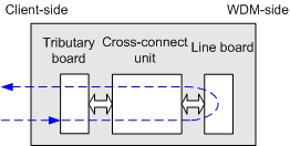
2-  In-loop on an OTN Line Board  : this loop is used to check whether the board properly processes received Signals
9


D-SDH Board Loopback:  We have out-loops and In-Loops on Optical interface on SDH boards as the Following:

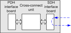
1-   Out-loop on the SDH optical interface board: this loop is used to check whether the SDH interface and the external cable of the SDH board are normal and the loop does not change the signal structure within the optical interface board by the signal that is transmitted from the optical receiver module is directly looped from the SDH interface to the optical transmitter module.

10


2-   VC-4 out-loop on the SDH optical interface board: The loop checks whether the VC-4 channels at the SDH interfaces and on the fibers connected to the SDH board are normal and does not change the signal structure within the optical interface board where the VC-4 signal that is transmitted from the optical receiver module is directly looped from the VC-4 channel to the optical transmitter module

.

11


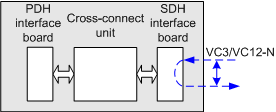
3-  VC-3/VC-12 Out-loop on the SDH optical interface board: the loop checks The VC-3/VC-12 outloop does not change the signal structure within the optical interface board where the VC-3/VC-12 signal that is transmitted from the optical receiver module is directly looped from the VC-3/VC-12 channel to the optical transmitter module.

12


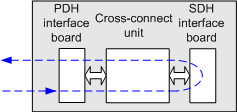
4- In-loop on the SDH optical interface board: The loop is used to check whether the SDH service processing module and the cross-connect board are normal a via The optical interface in-loop processes the signal at the local end within the optical interface board, where the signal that is transmitted from the cross-connect unit is looped from the SDH interface to the cross-connect unit

13


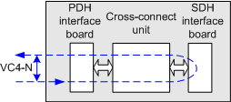
5-      VC-4 in-loop on the SDH optical interface boardThe loop checks whether the SDH service processing module and the cross-connect board are normal a via The VC-4 In-loop processes the signal at the local end within the optical interface board Where the VC-4 signal that is transmitted from the cross-connect unit is looped from the VC-4 channel to the cross-connect unit

14


E-PDH Board Loopback: We can through PDH board apply in-loop and out-loop to test electric interface Board as the following

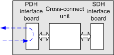
1-  Out-loop on the PDH Electrical interface boardThe loop checks whether the PDH interface and the external cable of the PDH board are normal and does not change the signal structure within the PDH electrical interface board where the signal that is transmitted from the receive port is directly looped back to the corresponding transmit port before being processed.

15


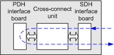
 2-   In-loop on the PDH Electrical interface boardThe loop checks whether the PDH service processing module and the cross-connect board are normal by processing the signal at the local end within the PDH electrical interface board Where the signal that is transmitted from the cross-connect unit is looped back to the cross-connect unit

16


F-Ethernet Board Loopback: Through ETH Board we are Classified In-loop on ETH port into

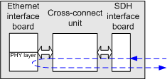
1-      In-loop PHY Port Layer Loopback: the loop checks whether the MAC layer, SDH layer, and signals of the Ethernet board are normal where the Ethernet service that is transmitted from the NE is looped from the physical layer of the Ethernet port to the SDH layer

17


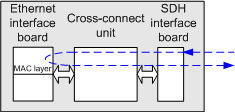
2-      In-loop MAC Port Layer Loopback: this loop checks whether the SDH layer and signals of the Ethernet board are normal where the Ethernet service that is transmitted from the NE is looped from the MAC layer of the Ethernet port to the SDH layer

18


Finally, I hope that my technical post helps everyone to know how to make Loopback on mentioned Boards to test Optical interface, Electric interface, Connectors, Cables, Modules and Cross-Connection.

Thursday, March 4, 2021

CE6863 CE6881 CE6881E 600 W AC&240 V DC Power Module Introduction

Huawei CE6863 CE6881 CE6881E like CE6863-48S6CQ 600 W AC&240 V DC power modules can receive AC inputs or 240 V high-voltage DC inputs. They are classified into two types depending on the airflow designs:

PAC600S12-CB (B: back-to-front airflow, air exhaust on power module panel)

PAC600S12-CF (F: front-to-back airflow, air intake on power module panel).


Appearance

Figure 1 shows the appearance of the PAC600S12-CB power module, and Figure 2 shows the appearance of the PAC600S12-CF power module.

Figure 1 PAC600S12-CB power module


Figure 2 PAC600S12-CF power module


Function

PAC600S12-CB and PAC600S12-CF power modules use different airflow designs but have the same functions. Table 2 describes the functions of them.


Note

When a power module enters overtemperature protection state, take measures to lower its temperature. The power module can automatically resume power supply when the temperature falls within the normal range.

Panel

Figure 3 and Figure 4 show the panels of 600 W AC&240 V DC power modules.

Figure 3 Panel of the PAC600S12-CB power module


Figure 4 Panel of the PAC600S12-CF power module

Tuesday, February 23, 2021

How to back Up the NE Database to Huawei OTN SCC Board on U2000?

You need to back up the NE database during daily maintenance, to ensure that OSN6800 OSN8800 SCC board of the NE automatically restores to normal operation after a data loss or equipment power failure. When you back up the NE database to the SCC board, you actually back up the NE data in the DRDB database of the SCC board to the Flash database. When the NE is restarted after a power failure, the SCC board automatically reads the configuration from the FLASH and issues the configuration to the boards.

Prerequisite

You must be an NM user with "NE administrator" authority or higher.

You must log in to the NE as an NE user with system level authority.

Tools, Equipment and Materials

NMS or Web LCT

Precautions

Note: By default, the NMS automatically backs up the NE database into the flash memory every 30 minutes.

Procedure on the NMS

1,Visit the following navigation path.


2, Back up the NE database to the TN52SCC or TN11SCC board.


Procedure on the Web LCT

1, Select one or more NEs in the NE list. Click BackUp NE Database BackUp to SCC.

Note: The NMS takes a few minutes to back up the NE database. Do not perform any operation in the process of backup.

2, Click OK in the confirmation dialog box.

3, Click Close in the Operation Result dialog box is displayed.


Friday, January 22, 2021

Why ME60-X8 LPU or SFU Board Cannot Be Registered?

Sometimes ME60-X8 card LPU or SFU cannot to be registered, what are the caused and how to check the problems, thsi article will show how to troubleshot.

Common Causes

This fault is commonly caused by one of the following:


  • The board has not finished start-up yet.
  • The board type is not supported by the system software.
  • The board fails to be powered on.
  • The EPLD, BootROM, and BootLoad of the board have not been upgraded.
  • The board is not securely inserted.

roubleshooting Flowchart

Figure 1 shows the troubleshooting flowchart.

Figure 1 Troubleshooting flowchart for the fault that an interface board or SFU such as SFUI-200-C ME0DSFUIE07C cannot be registered


Troubleshooting Procedure

Saving the results of each troubleshooting step is recommended. If your troubleshooting fails to correct the fault, you will have a record of your actions to provide Huawei technical support personnel.

Procedure

  1. Check that the start-up time of the board has expired.

    The time required for a board to complete registration after it is powered on is called the start-up time.

    Normally, an SFU can complete the start-up process within 2 minutes. If the system software and related files need to be updated, an SFU can complete the start-up process within 5 minutes.

    Wait until the start-up time expires. If the board is still unregistered when the start-up time expires, go to Step 2.

  2. Check that the board type is supported by the system software.

    Supported board types vary with system software versions. For the types of boards that are supported by this software version, see the chapter titled "Boards" in the HUAWEI ME60 Multiservice Control Gateway Hardware Description.

    If the board type is supported by this system software version but the board cannot be registered, go to Step 3.

  3. Check that the board has been powered on.

    Run the power on slot ? command in the user view. If "<null>" is displayed, it indicates that all boards have been powered on.

    If the slot number of the board is displayed, it indicates that the board is not powered on. Check whether the power supply of the slot where the board resides is normal. If the indicator on the board is on, it indicates that the power supply of this slot is normal.

    • If the power supply of the slot is abnormal, contact Huawei technical support personnel.
    • If the power supply of the slot is normal but the system still prompts that the board is not powered on, it indicates that the power supply module on the board is faulty. In this case, you need to replace the board.

    If the power supply of the board is normal but the board cannot be registered, go to Step 4.

  4. Upgrade the EPLD of the board.

    Run the upgrade lpu by-testbus slot-id startup lpu_epld and upgrade lpu by-testbus slot-id startup lpu_epld2 commands in the user view to upgrade the EPLD of the interface board.

    Run the upgrade sfu by-testbus slot-id startup mbus_epldupgrade sfu by-testbus slot-id startup sfu_epld1, and upgrade sfu by-testbus slot-id startup sfu_epld2 commands in the user view to upgrade the EPLD of the SFU.

    If the board still cannot be registered after the EPLD is upgraded, go to Step 5.

  5. Upgrade the BootROM and BootLoad of the board.

    Run the upgrade lpu by-testbus slot-id startup lpu_bootrom and upgrade lpu by-testbus slot-id startup lpu_bootload commands in the user view to upgrade the BootROM and BootLoad of an interface board.

    Run the upgrade sfu by-testbus slot-id startup sfu_bootrom and upgrade sfu by-testbus slot-id startup sfu_bootload commands in the user view to upgrade the BootROM and BootLoad of the concerned SFU.

    If the board still cannot be registered after the EPLD is upgraded, go to Step 6.

  6. If a new board cannot be registered, remove the board and then insert it back. If the board still cannot be registered, go to Step 7.
  7. Collect the following information and contact Huawei technical support personnel.

    • Results of the preceding troubleshooting operations
    • Configuration files, log files, and alarm files of the device

Thursday, January 7, 2021

What is Huawei Switch Port Mirroring & How to use it?

 1. Application Scenario

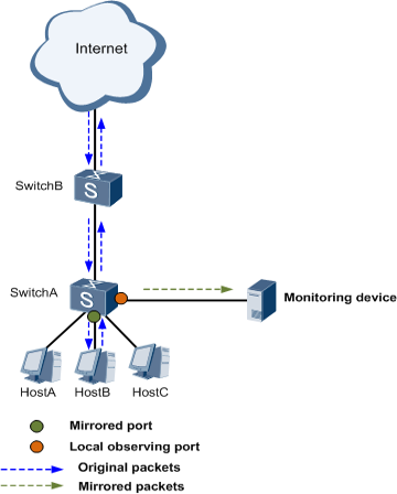
Mirroring is a function that copies packets on a specified port (source port or mirrored port) to another specified port (destination port or observing port).

During network operation and maintenance, network administrators often need to obtain and analyze packets on devices for service monitoring and fault location purposes.

The mirroring function copies packets on a mirrored port to an observing port without affecting packet processing on devices. Network administrators can analyze the copied packets sent from an observing port to a monitoring device to determine whether services running on a network are normal.


A


2. Configuration Roadmap


(1) Configure the port that connects Huawei Switch A to the monitoring device as an observing port.


(2) Configure the port that packets to be mirrored pass through as a mirrored port to mirror the received or sent packets to the observing port.


(3) Start the monitoring software on the monitoring device to obtain mirrored packets.


3. Procedure


(1) Configure GE0/0/20 on Switch A as an observing port.


[SwitchA] observe-port 1 interface gigabitethernet 0/0/20


(2) Mirror the packets received by GE0/0/7 to the observing port


[SwitchA] interface gigabitethernet 0/0/7

[SwitchA- GigabitEthernet0/0/7] port-mirroring to observe-port 1 inbound

[SwitchA- GigabitEthernet0/0/7] quit


(3) Start a packet analyzer software on the monitoring device.

2


If you have still have problem to use Huawei switch like S3700 S5700 S6700 S6720 port mirroring, you can contact thunder-link.com support teams. 


More related products

Huawei ME60 BRAS

Huawei CE6800 CE8800 switches