Thursday, July 15, 2021

How to configure the xDSL Service in PPPoE Mode on MA5600T

On a fiber to the x (FTTx) network, if the MA5600T/MA5603T/MA5608T provides x digital subscriber line (xDSL) services for broadband users and the users connect to the Internet in Point-to-Point Protocol over Ethernet (PPPoE) dialup mode, you can configure the MA5600T/MA5603T/MA5608T by referring to this topic to provide users with high-speed Internet (HIS) services. The MA5600T/MA5603T/MA5608T functions as an optical network unit (ONU) in this service. PPPoE is a commonly used Internet access mode currently. In this mode, broadband users are authenticated, authorized, and charged in Authentication, Authorization and Accounting (AAA) method.

Service Requirements

  • The user accesses the Internet through the PPPoE dialup.
  • The user packet goes upstream carrying two VLAN tags. The outer VLAN tag identifies the service and the inner VLAN tag identifies the user. The service of each user is identified by unique S-VLAN+C-VLAN, that is, this is a 1:1 access scenario.
  • A traffic profile is adopted for rate limitation. The user access rate is 2048 kbit/s.
  • To ensure reliability, dual GE ports are adopted for upstream transmission, and link aggregation is configured for the two upstream ports.

Figure 1 shows an example network of the xDSL Internet access service through the PPPoE dialup.

Figure 1 Example network of the xDSL Internet access service through the PPPoE dialup


Prerequisite

  • The AAA function must be configured.
    • To enable the AAA function on the device, see Configuring the Local AAA.
    • If the AAA function is implemented by the BRAS, a connection to the BRAS must be established. The BRAS should be capable of identifying the VLAN tag of the MA5600T/MA5603T/MA5608T in the upstream direction. For the identification purpose, the user name and password for dial-up Internet access must be configured on the BRAS.

Procedure

  1. Configure a VLAN.

    Configure S-VLAN 50 with the stacking attribute. The user packet goes upstream carrying two VLAN tags. The outer VLAN tag identifies the service and the inner VLAN tag identifies the user. The service of each user is identified by unique S-VLAN+C-VLAN, and the VLAN forwarding mode is the S-VLAN+C-VLAN mode.

    huawei(config)#vlan 50 smart  
    huawei(config)#vlan attrib 50 stacking 
    huawei(config)#vlan forwarding 50 vlan-connect
  2. Configure upstream ports.

    Add upstream ports 0/19/0 and 0/19/1 to VLAN 50. Two ports are added for the purpose of port aggregation.

    huawei(config)#port vlan 50 0/19 0   
    huawei(config)#port vlan 50 0/19 1  
    

    To aggregate the two upstream ports as one aggregation group, set the packet forwarding mode of the aggregation group to egress-ingress, and set the aggregation group to work in the LACP static mode, do as follows:

    huawei(config)#link-aggregation 0/19 0 0/19 1 egress-ingress workmode lacp-static
    NOTE:

    The aggregated ports must meet the following requirements: The ports must work in the full-duplex mode; the port rates must be the same and the rate of an electrical port must not be of the auto-negotiation type; the attributes of the ports, such as the default VLAN ID (PVID) and VLAN, must be the same; one port can belong to only one aggregation group; the port must not be a mirroring destination port; the port must not be in the auto-negotiation mode; the start port ID must be smaller than the end port ID.

  3. In the ADSL access mode, follow this procedure.
    1. Configure an ADSL2+ profile. For details, see Overview of Configuring ADSL2+ Templates and Profiles. The default ADSL2+ line template (line template 1) and the default ADSL2+ alarm template (alarm template 1) are used as an example.
    2. Activate the ADSL port, and bind the ADSL2+ templates.

      NOTE:

      By default, an ADSL port is in the activated state. Before binding a template to the port, you must deactivate the port.

      In the ADSL access mode, bind the default ADSL2+ line template 1 and ADSL2+ alarm template 1 to ADSL port 0/2/0.

      huawei(config)#interface adsl 0/2
      huawei(config-if-adsl-0/2)#deactivate 0
      huawei(config-if-adsl-0/2)#activate 0 profile-index 1
      huawei(config-if-adsl-0/2)#alarm-config 0 1
      huawei(config-if-adsl-0/2)#quit

    3. Run the display traffic table command to query the existing traffic profiles in the system.

      huawei(config)#display traffic table ip from-index 0
      { <cr>|to-index<K> }:
      
        Command:
                display traffic table ip from-index 0
        ---------------------------------------------------------------------------
         TID CIR      CBS      PIR      PBS      Pri Copy-policy         Pri-Policy
             (kbps)   (bytes)  (kbps)   (bytes)
        ---------------------------------------------------------------------------
           0 1024     34768    2048     69536      6 -                      tag-pri
           1 2496     81872    4992     163744     6 -                      tag-pri
           2 512      18384    1024     36768      0 -                      tag-pri
           3 576      20432    1152     40864      2 -                      tag-pri
           4 64       4048     128      8096       4 -                      tag-pri
           5 2048     67536    4096     135072     0 -                      tag-pri
           6 off      off      off      off        0 -                      tag-pri
        ---------------------------------------------------------------------------
        Total Num : 7

      According to service requirements, the user access rate is 2048 kbit/s. The query result shows that traffic profile 5 (for inbound and outbound rate limitation) meets the requirements.

      NOTE:
      • If a matched traffic profile is not available in the system, run the traffic table ip command to configure a new traffic profile.
      • On the MA5600T/MA5603T/MA5608T, the user access rate can be limited by either a traffic profile or an ADSL line profile. When both profiles are configured, the smaller one of the two rates configured in the profiles is adopted as the user bandwidth. In this example, the traffic profile is used to limit the user access rate.

    4. Run the service-port command to create a service port, adopt traffic profile 5, and set the S-VLAN ID to 50. The index of the service port is 1, and the VPI and VCI of the service port must be the same as the management VPI and VCI of the peer modem. Assume that the management VPI and VCI of the modem are 1 and 39, and the access port ID is 0/2/0. To facilitate the maintenance of the service port, also configure the service port description.
      huawei(config)#service-port 1 vlan 50 adsl 0/2/0 vpi 1 vci 39 inbound traffic-table index 5 outbound traffic-table index 5    
      huawei(config)#service-port desc 1 description Vlanid:50/adsl/vpi:1vci:39/stacking 
    5. Set the C-VLAN ID of the preset service port 1 to 10 for identifying the user. Configure the important user packet with a higher priority so that the user packet can be processed with precedence, and set the priority of the inner VLAN to 4.
      huawei(config)#stacking label service-port 1 10 
      huawei(config)#stacking inner-priority service-port 1 4
      
  4. In the SHDSL access mode, follow this procedure.
    1. Configure an SHDSL profile. For details, see Configuring SHDSL Profiles. Add SHDSL line profile 3 of the PTM type, with the maximum line rate 2048 kbit/s.
      huawei(config)#shdsl line-profile quickadd 3 ptm rate 512 2048 
    2. Activate SHDSL port 0/3/1, and bind the preset SHDSL line profile 3 and the default SHDSL alarm template (alarm template 1) to the port.

      NOTE:

      By default, an SHDSL port is in the activated state. Before binding a profile or template to the port, you must deactivate the port.

      huawei(config)#interface shl 0/3 
      huawei(config-if-shl-0/3)#deactivate 1
      huawei(config-if-shl-0/3)#activate 1 3
      huawei(config-if-shl-0/3)#alarm-config 1 1 
      huawei(config-if-shl-0/3)#quit 

    3. Run the display traffic table command to query the existing traffic profiles in the system.

      huawei(config)#display traffic table ip from-index 0
      { <cr>|to-index<K> }:
      
        Command:
                display traffic table ip from-index 0
        ---------------------------------------------------------------------------
         TID CIR      CBS      PIR      PBS      Pri Copy-policy         Pri-Policy
             (kbps)   (bytes)  (kbps)   (bytes)
        ---------------------------------------------------------------------------
           0 1024     34768    2048     69536      6 -                      tag-pri
           1 2496     81872    4992     163744     6 -                      tag-pri
           2 512      18384    1024     36768      0 -                      tag-pri
           3 576      20432    1152     40864      2 -                      tag-pri
           4 64       4048     128      8096       4 -                      tag-pri
           5 2048     67536    4096     135072     0 -                      tag-pri
           6 off      off      off      off        0 -                      tag-pri
        ---------------------------------------------------------------------------
        Total Num : 7

      According to service requirements, the user access rate is 2048 kbit/s. The query result shows that traffic profile 5 (for inbound and outbound rate limitation) meets the requirements.

      NOTE:
      • If a matched traffic profile is not available in the system, run the traffic table ip command to configure a new traffic profile.
      • On the MA5600T/MA5603T/MA5608T, the user access rate can be limited by either a traffic profile or an SHDSL line profile. When both profiles are configured, the smaller one of the two rates configured in the profiles is adopted as the user bandwidth. In this example, the traffic profile is used to limit the user access rate.

    4. Run the service-port command to create a service port, adopt traffic profile 5, and set the S-VLAN ID to 50. Set the SHDSL channel mode to PTM, and create service port 2 on SHDSL port 0/3/1. To facilitate the maintenance of the service port, also configure the service port description.
      huawei(config)#service-port 2 vlan 50 shdsl mode ptm 0/3/1 inbound traffic-table
       index 5 outbound traffic-table index 5
      huawei(config)#service-port desc 2 description Vlanid:50/shdsl/vpi:1vci:39/stacking
    5. Set the C-VLAN ID of the preset service port 2 to 10 for identifying the user. Configure the important user packet with a higher priority so that the user packet can be processed with precedence, and set the priority of the inner VLAN to 4.
      huawei(config)#stacking label service-port 2 10
      huawei(config)#stacking inner-priority service-port 2 4 
  5. In the VDSL access mode, follow this procedure.

    In this example, the VDSL normal mode is used as an example.

    1. Configure a VDSL profile. For details, see Overview of Configuring VDSL2 Templates and Profiles. Assume that the VDSL profile ID is 3, downstream rate is 2048 kbit/s, channel mode is the interleave mode, maximum downstream interleave delay is 8 ms, maximum upstream interleave delay is 2 ms, SNR margin is 6 dB, minimum downstream INP is 4, and minimum upstream INP is 2.
      huawei(config)#vdsl line-profile quickadd 3 snr 60 0 300 60 0 300
      huawei(config)#vdsl channel-profile quickadd 3 path-mode ptm interleaved-delay 8 2 inp 4 2 rate 
      128 10000 128 10000 2048 2048
      huawei(config)#vdsl line-template quickadd 3 line 3 channel1 3 100 100
    2. Activate VDSL port 0/4/1, and bind the preset VDSL line template 3 and the default VDSL alarm template (alarm template 1) to the port.

      NOTE:

      By default, a VDSL port is in the activated state. Before binding a template to the port, you must deactivate the port.

      huawei(config)#interface vdsl 0/4 
      huawei(config-if-vdsl-0/4)#deactivate 1 
      huawei(config-if-vdsl-0/4)#activate 1 template-index 3
      huawei(config-if-vdsl-0/4)#alarm-config 1 1 
      huawei(config-if-vdsl-0/4)#quit 

    3. Run the display traffic table command to query the existing traffic profiles in the system.

      huawei(config)#display traffic table ip from-index 0
      { <cr>|to-index<K> }:
      
        Command:
                display traffic table ip from-index 0
        ---------------------------------------------------------------------------
         TID CIR      CBS      PIR      PBS      Pri Copy-policy         Pri-Policy
             (kbps)   (bytes)  (kbps)   (bytes)
        ---------------------------------------------------------------------------
           0 1024     34768    2048     69536      6 -                      tag-pri
           1 2496     81872    4992     163744     6 -                      tag-pri
           2 512      18384    1024     36768      0 -                      tag-pri
           3 576      20432    1152     40864      2 -                      tag-pri
           4 64       4048     128      8096       4 -                      tag-pri
           5 2048     67536    4096     135072     0 -                      tag-pri
           6 off      off      off      off        0 -                      tag-pri
        ---------------------------------------------------------------------------
        Total Num : 7

      According to service requirements, the user access rate is 2048 kbit/s. The query result shows that traffic profile 5 (for inbound and outbound rate limitation) meets the requirements.

      NOTE:
      • If a matched traffic profile is not available in the system, run the traffic table ip command to configure a new traffic profile.
      • On the MA5600T/MA5603T/MA5608T, the user access rate can be limited by either a traffic profile or a VDSL line profile. When both profiles are configured, the smaller one of the two rates configured in the profiles is adopted as the user bandwidth. In this example, the traffic profile is used to limit the user access rate.

    4. Run the service-port command to create a service port, adopt traffic profile 5, and set the S-VLAN ID to 50. Set the VDSL channel mode to PTM, and create service port 3 on VDSL port 0/4/1. To facilitate the maintenance of the service port, also configure the service port description.
      huawei(config)#service-port 3 vlan 50 vdsl mode ptm 0/4/1 inbound traffic-table 
      index 5 outbound traffic-table index 5
      huawei(config)#service-port desc 3 description Vlanid:50/vdsl/vpi:1vci:39/stacking
    5. Set the C-VLAN ID of the preset service port 3 to 10 for identifying the user. Configure the important user packet with a higher priority so that the user packet can be processed with precedence, and set the priority of the inner VLAN to 4.
      huawei(config)#stacking label service-port 3 10 
      huawei(config)#stacking inner-priority service-port 3 4  
  6. Configure the user account security.

    The PITP P mode can be enabled to protect the user account against theft and roaming. The RAIO mode can be customized according to actual requirements. The encoding format required by China Telecom is considered as an example. The encoding format required by China Telecom is a customized format, corresponding to the cntel option.

    huawei(config)#pitp enable pmode
    huawei(config)#raio-mode cntel pitp-pmode 
    NOTE:
    For details about the PITP configuration for the user account security, see Configuring Anti-theft and Roaming of User Accounts Using PITP.
  7. Save the data.
    huawei(config)#save

Verification

  • Dialing verification on the user side:
    • Step 1: Configure the user name and password for the dialup on the modem (the user name and password must be the same as those configured on the BRAS).
    • Step 2: Dial up on the PC by using the PPPoE dialup software. After the dialup is successful, the user can access the Internet.
    • Step 3: When FTP is used to download files, after the dialup is performed on the PPPoE dialup software, the PPPoE dialup software prompts that the dialup is successful. Then, the PC can access the Internet in the PPPoE mode.
    • Step 4: When downloading files through FTP, you can open Task Manager in Windows and click Networking to check the link speed. Then, you can calculate the Internet access rate by the following formula: Attainable Internet access rate = Computer network adapter rate/48 x 53 x 8. The calculation result approximates to the planned 2048 kbit/s.
  • Remote emulation dialing verification:
    • Step 1: On the MA5600T/MA5603T/MA5608T, run the pppoe simulate start command to start the PPPoE emulation dialer (the entered user name, password, and authentication mode must be the same as those configured on the BRAS).
    • Step 2: Run the display pppoe simulate info command to query status of PPPoE emulation dialing. If the PPPoE emulation dialing result is success, that is, simulating interaction between the user and the BRAS is successful, the user can access the Internet in the PPPoE access mode.
    • After the emulation verification is completed, run the pppoe simulate stop command to stop the PPPoE emulation dialing task initiated by the user.

Configuration File

Configuration File in the ADSL access mode:

vlan 50 smart  
vlan attrib 50 stacking 
vlan forwarding 50 vlan-connect
port vlan 50 0/19 0
port vlan 50 0/19 1
link-aggregation 0/19 0 0/19 1 egress-ingress workmode lacp-static
interface adsl 0/2
deactivate 0
activate 0 profile-index 1
alarm-config 0 1
quit
service-port 1 vlan 50 adsl 0/2/0 vpi 1 vci 39 inbound traffic-table index 5 outbound traffic-table index 5 
service-port desc 1 description Vlanid:50/adsl/vpi:1vci:39/stacking
stacking label service-port 1 10
stacking inner-priority service-port 1 4
pitp enable pmode
raio-mode cntel pitp-pmode 
save

Configuration File in the SHDSL access mode:

vlan 50 smart  
vlan attrib 50 stacking 
vlan forwarding 50 vlan-connect
port vlan 50 0/19 0
port vlan 50 0/19 1
link-aggregation 0/19 0 0/19 1 egress-ingress workmode lacp-static
shdsl line-profile quickadd 3 ptm rate 512 2048 
interface shl 0/3
deactivate 1
activate 1 3
alarm-config 1 1
quit
service-port 2 vlan 50 shdsl mode ptm 0/3/1 inbound traffic-table index 5 outbound traffic-table index 5
service-port desc 2 description Vlanid:50/shdsl/vpi:1vci:39/stacking
stacking label service-port 2 10  
stacking inner-priority service-port 2 4 
pitp enable pmode
raio-mode cntel pitp-pmode 
save

Configuration File in the VDSL access mode:

vlan 50 smart  
vlan attrib 50 stacking 
vlan forwarding 50 vlan-connect
port vlan 50 0/19 0
port vlan 50 0/19 1
link-aggregation 0/19 0 0/19 1 egress-ingress workmode lacp-static
vdsl line-profile quickadd 3 snr 60 0 300 60 0 300
vdsl channel-profile quickadd 3 path-mode ptm interleaved-delay 8 2 inp 4 2 rate 
128 10000 128 10000 2048 2048
interface vdsl 0/4
deactivate 1
activate 1 template-index 3
alarm-config 1 1
quit
service-port 3 vlan 50 vdsl mode ptm 0/4/1 inbound traffic-table index 5 outbound traffic-table index 5
service-port desc 3 description Vlanid:50/vdsl/vpi:1vci:39/stacking
stacking label service-port 3 10
stacking inner-priority service-port 3 4 
stacking inner-priority service-port 2 4 
pitp enable pmode
raio-mode cntel pitp-pmode 
save

Thursday, June 24, 2021

Do you know DSLAM Vectoring VDSL2 Crosstalk NEXT and FEXT?

 VDSL2 Crosstalk Classifications

VDSL2 crosstalk on DSLAM is classified as near-end crosstalk (NEXT) and far-end crosstalk (FEXT).

Figure shows the crosstalk of the two types.


  • In NEXT, TX signals are sent from the interfering pair, coupled to the interfered pair, and then sent to the near-end RX end of the interfered pair. For example, in a bundle of lines, when signals in the upstream direction of a line interfere with signals in the downstream direction of an adjacent line, or signals in the downstream direction of a line interfere with signals in the upstream direction of an adjacent line, NEXT occurs.
  • In FEXT, TX signals are sent from the interfering pair, coupled to the interfered pair, and then sent along the interfered pair to the far-end RX end of the interfered pair. For example, in a bundle of lines, when signals in the upstream direction of a line interfere with signals in the upstream direction of an adjacent line, or signals in the downstream direction of a line interfere with signals in the downstream direction of an adjacent line, FEXT occurs.

In other words, NEXT is interference between upstream signals and downstream signals of different pairs, and FEXT is interference between upstream signals or between downstream signals of different pairs.

How Can We Eliminate NEXT and FEXT

  • VDSL2 uses the frequency division multiplexing (FDM) technology to transmit data. Therefore, TX signals of the interfering pair and RX signals of the interfered pair use different frequencies. Therefore, the impact of NEXT can be eliminated or mitigated using a filter.
  • TX signals of the interfering pair cannot be eliminated using a filter because these signals use the same frequency band as the RX signals of the interfered pair. In addition, VDSL2 uses a high frequency band (up to 30 MHz) for short-distance transmission (usually within 1.2 km). As a result, FEXT has a more severe effect on VDSL2 than on other DSL access modes. Therefore, FEXT is the main factor of degrading VDSL2 performance. To eliminate FEXT, the ITU-T Recommendation promoted G.993.5-compliant vectoring.
NOTE:
  • To eliminate or mitigate crosstalk, the DSL industry promoted a series of techniques totally called the dynamic spectrum management (DSM) technology. The DSM technology involves four stages, level 0 through level 3 stages. At level 0 through level 2 stages, the AN manages the spectra of the TX signals of single- or multi-DSL pairs, which eliminates FEXT only to a certain extend. To completely cancel FEXT on VDSL2 lines, the ITU-T Recommendation launched vectoring. Vectoring uses vectors to cancel FEXT on VDSL2 lines, thereby significantly improving the bandwidth and performance of multi-pair VDSL2 lines. Therefore, vectoring is also called level-3 DSM.
  • Vectoring can significantly eliminate only FEXT.

Friday, June 4, 2021

ONT Fails to Be Added to the MA5608T Because the H808EPSD Version Is Low

 Contents

Issue Description

On Huawei MA5608T+H808EPSD, the system prompts that the board does not support this operation when confirming an automatically discovered ONT.

Alarm Information

0x023100ed Board Software Automatic Expansion Failure

Handling Process

1. Run the display board command to check whether the status of each board is normal.


2. Run the display alarm active all command to query the alarms. The command output shows the 0x023100ed Board Software Automatic Expansion Failure alarm on the H808EPSD board.


3. Run the display io-packetfile information command, output shows that there is no I/O package of H808EPSD.


4. Run the display version command, the output shows that the version of the MCUD control board is V800R017C00 and the software app version of the H808EPSD board is 2013. The version difference is large.


5. Load the combined package of the V800R017C00 version and add the I/O package of the H808EPSD board. The issue is solved.

Root Cause

The H808EPSD board software is not upgraded to the latest version. As a result, the board status is normal, but the board cannot carry services or the services are limited.

Solution

Upgrade the software of the H808EPSD board to the latest version.

Suggestions

When a user interface board is inserted, the version information about the board is reported to the system. If the version of the board software is inconsistent with that of the board software stored in the flash of the control board, the system automatically loads the software. If the automatic loading fails, the system generates the alarm 0x2420a003 Automatic Loading Failure. Impact of the alarm on the system: The board software of the interface board is not upgraded to the latest version. As a result, the board cannot carry services or the services are limited.

Thursday, May 27, 2021

Why EGS4 prevents LACP protocol packets from being transparently transmitted?

 Problem Description

The link aggregation function is activated between two switches in a certain office. One port uses the dedicated line service configured by EGS4 and EGS2 of OSN3500, and the other port uses optical fiber to connect directly. When the switch starts manual aggregation (without LACP protocol), the service is normal. But when it is configured as static aggregation (LACP protocol is started), the service fails. The attributes of the external ports of the EGS4 and EGS2 boards are Hybrid. The switch on the EGS4 side can receive LACP packets, but the EGS2 switch cannot receive LACP packets.


Warning message


No abnormal transmission alarm


Process


1. Since the business is normal when using manual aggregation, it is certain that there is no problem with the transmission channel.

2. The difference between static aggregation and manual aggregation is that it uses the LACP protocol. Therefore, when static aggregation is suspected, the cause of service failure is that LACP protocol packets are not transparently transmitted to the peer device.

3. The LACP protocol does not have a VLAN tag. It should be no problem if the port attribute is set to Hybrid. It is suspected that the ingress port of the egs4 board does not transparently transmit LACP packets.

4. After confirming that the egs4 board supports the LACP protocol, when the external port receives the LACP message, it will be sent to the CPU for processing instead of transparently transmitting the LACP message. In this case, you need to set the port's "ingress detection" function as "Prohibited"

5. The static link aggregation service of the switch is normally opened after setting the "ingress detection" of the port


Root cause


1. The EGS4 board supports the LACP protocol. When the external port receives the LACP message, it will be sent to the CPU for processing and will not transparently transmit the LACP message. If the LACP message needs to be transparently transmitted, it is necessary to set the port's "ingress detection" "The function is "Prohibited".

2. The EGS2 board port does not support the LACP protocol, and treats LACP packets as ordinary Ethernet packets, so LACP packets can be detected in one direction.


Conclusions


At the same time, I learned that SSN5EFS0 also has this problem. When you need to transparently transmit LACP packets, you need to pay attention to the "ingress detection" attribute configuration.

Thursday, April 29, 2021

How to checking the Temperature of Each Board on Huawei Router?

 This section describes how to verify Huawei router like NE40E ME60-X8 boards temperature

Prerequisites

The router has been logged in to.

Procedure

  1. Run the display temperature[ [ lpu | mpu | sfu ] slot slot-id [ pic pic-id ] ] command to view the temperature status on each board

    <HUAWEI> display temperature
    SlotID2
     Base-Board, Unit:C, Slot2
    PCB   I2C Addr Chl  Status  Minor Major Fatal Adj_speed Temp
                                                  TMin Tmax (C)
    -----------------------------------------------------------------
    LPUF  1   1    0    NORMAL  70    80    90    60   70   36
    LPUF  1   2    0    NORMAL  60    70    80    50   60   33
    LPUF  1   4    0    NORMAL  70    80    90    60   70   35
    LPUF  1   5    0    NORMAL  80    90    100   70   80   39
    LPUF  1   6    0    NORMAL  70    80    90    60   70   38
    LPUF  2   76   1    NORMAL  90    96    102   80   90   39
    LPUF  2   76   2    NORMAL  90    96    102   80   90   40
    TCMB  1   3    0    NORMAL  70    80    90    60   70   34
    TCMB  1   7    0    NORMAL  60    70    80    50   60   31

    Pay attention to the values of boldfaced fields displayed. The Temp(C) field indicates the current temperature. The Minor field indicates the threshold of a high temperature for a minor alarm. The Major field indicates the threshold of a high temperature for a major alarm. The Fatal field indicates the threshold of a high temperature for a critical alarm. If the board temperature reaches or exceeds the value of the Fatal field, Huawe ME60 may work abnormally or be damaged.

    If the displayed value of the Temp(C) field is lower than that of the Minor field, the board temperature is normal. Then, go on with the subsequent commissioning.

Troubleshooting

If the board temperature exceeds the threshold, perform the following operations:

  1. Check whether fans are faulty and replace any faulty fans.

  2. Check whether the air filter is clogged. If it is clogged, clean it.

  3. Check whether the ambient temperature is too high. If the ambient temperature is too high, lower the temperature in the equipment room.

  4. If the board temperature is still high after the preceding operations, it is due to the high chip temperature. In this case, no action is required or contact Huawei technical support personnel.

Thursday, April 15, 2021

What are the BGP VPNv4 and Labeled BGP routes?

During the studying of MPLS VPN, we usually encounter the VPNv4 and Labeled BGP routes of Huawei switch and Router. A lot of people can't distinguish between them. Actually, they are so different from each other.


Before talking about the VPNv4 and the Labeled BFP routes, let's check the normal BGP route:


normal_bgp

The VPNv4 route


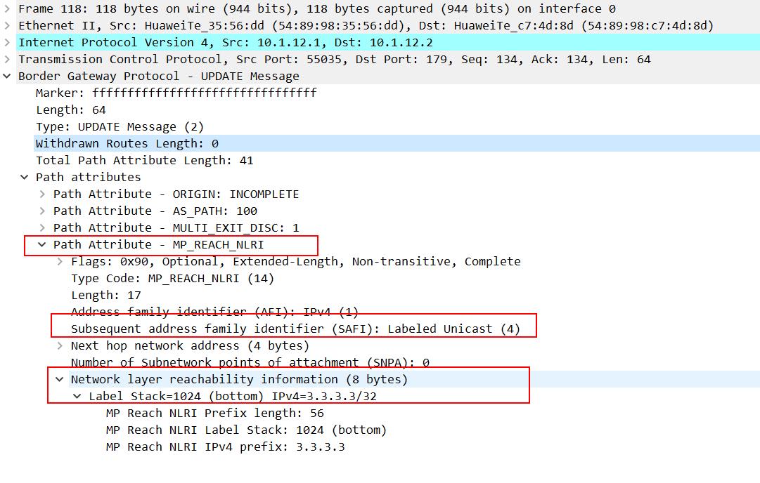
The VPNv4 route is comprised of two parts: the IPv4 route and the route-distinguisher. The route-distinguisher is used to distinguish the different VPN-instances. The router can forward the VPNv4 route to the appropriate VPN-instance. When the BGP updates the VPNv4 route, the RD (route-distinguisher) will be contained in the MP_REACH_NLRI field, just as the picture below shows. 


vpnv4

We noticed that a route-target value was attached in the EXTENDED_COMMUNITIES field. The route-target is used by the VPN-instance to decide whether the VPNv4 route will be accepted.


Labeled BGP route


Unlike the VPNv4 route, the Labeled BGP route is more similar to the normal BGP route. But the Labeled BGP route and the normal BGP route are also quite different.


In the Labeled BGP route, a MP_REACH_NLRI is attached as a VPNv4 BGP route does, but unlike the VPNv4 route, there is no RD or RT (route-target). It only carries a label stack, and the normal BGP route doesn't, just showing as the picture below:

label-BGP-route

The Labeled BGP route is used in MPLS VPN option C. Between the two ASBR, the labeled BGP route is transferred so that the label distributed by the different VPN-instances could pass through the different AS.


Friday, March 19, 2021

How do you Make Hardware and Software Loopback for OSN1800?

 How do you Make Hardware and Software Loopback for OSN1800?

The Loopback means of troubleshooting for Equipment and used to determine whether the boards, Optical interface, Electrical interface, Cables, Connectors and Cross-Connection are faulty

A.      OTU Board Loopback

B.      OTN Tributary Board Loopback

C.      OTN Line Board Loopback

D.     SDH Board Loopback

E.      PDH Board Loopback

F.       Ethernet Board Loopback

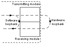
Hardware Loopback: Means an optical port connect the transmit end and receive end of the Port using a fiber and it must be performed onsite

Software Loopback: Means configure the Loop on the NMS

1

A-   OTU Board Loopback: A loopback is used to determine whether the board is faultyTypes of loopback which we can apply them on The OTU boards to verify the board SDH services as the following

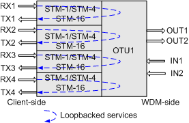
1-  Client –Side Out-loop  : this loop is used to detect whether the Fiber line and Connectors on the line are normal as the Following


2


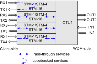
2-  Client –Side In-loop  : The loop is used to detect whether the received Signals are properly processed inside the board as the following 


3


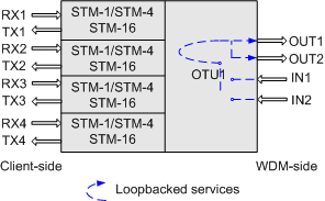
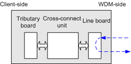
3-   WDM –Side In-loop  : this loop is used to detect whether the received Signals are properly processed inside the board as the following 


4


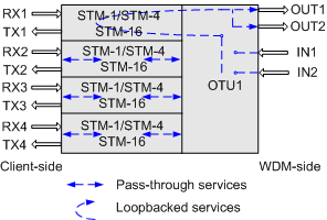
4-  WDM –Side out-loop  : The loop is used to detect whether the Fiber line and Connectors on the line are normal as the following 


5


B- OTN Tributary Board Loopback: An OTN tributary board we can do Inloop and Outloop to determine which Fault. The types of Loops as the following:

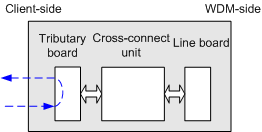
1-  Out-loop on the OTN Tributary Board  : this loop is used to Check whether optical Fibers and Connectors Functions properly  as the following 

6


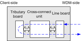
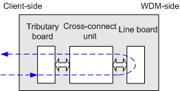
2-    In-loop on the OTN Tributary Board  : this loop is used to Check whether the board Properly processes received Signals as follows

7


 C-OTN Line Board LoopbackAn OTN line board which include In-Loop and Out-loop

1-  Out- loop on an OTN Line Board  : this loop is used to Check Fibers line and Connectors Function are Working Properly as follows

8


2-  In-loop on an OTN Line Board  : this loop is used to check whether the board properly processes received Signals

9


D-SDH Board Loopback:  We have out-loops and In-Loops on Optical interface on SDH boards as the Following:

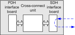
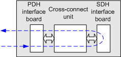
1-   Out-loop on the SDH optical interface board: this loop is used to check whether the SDH interface and the external cable of the SDH board are normal and the loop does not change the signal structure within the optical interface board by the signal that is transmitted from the optical receiver module is directly looped from the SDH interface to the optical transmitter module.


10


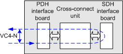
2-   VC-4 out-loop on the SDH optical interface board: The loop checks whether the VC-4 channels at the SDH interfaces and on the fibers connected to the SDH board are normal and does not change the signal structure within the optical interface board where the VC-4 signal that is transmitted from the optical receiver module is directly looped from the VC-4 channel to the optical transmitter module

.

11


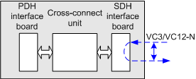
3-  VC-3/VC-12 Out-loop on the SDH optical interface board: the loop checks The VC-3/VC-12 outloop does not change the signal structure within the optical interface board where the VC-3/VC-12 signal that is transmitted from the optical receiver module is directly looped from the VC-3/VC-12 channel to the optical transmitter module.


12


4- In-loop on the SDH optical interface board: The loop is used to check whether the SDH service processing module and the cross-connect board are normal a via The optical interface in-loop processes the signal at the local end within the optical interface board, where the signal that is transmitted from the cross-connect unit is looped from the SDH interface to the cross-connect unit


13


5-      VC-4 in-loop on the SDH optical interface boardThe loop checks whether the SDH service processing module and the cross-connect board are normal a via The VC-4 In-loop processes the signal at the local end within the optical interface board Where the VC-4 signal that is transmitted from the cross-connect unit is looped from the VC-4 channel to the cross-connect unit


14


E-PDH Board Loopback: We can through PDH board apply in-loop and out-loop to test electric interface Board as the following

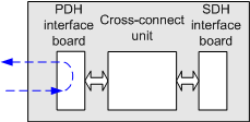
1-  Out-loop on the PDH Electrical interface boardThe loop checks whether the PDH interface and the external cable of the PDH board are normal and does not change the signal structure within the PDH electrical interface board where the signal that is transmitted from the receive port is directly looped back to the corresponding transmit port before being processed.


15


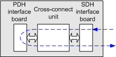
 2-   In-loop on the PDH Electrical interface boardThe loop checks whether the PDH service processing module and the cross-connect board are normal by processing the signal at the local end within the PDH electrical interface board Where the signal that is transmitted from the cross-connect unit is looped back to the cross-connect unit


16


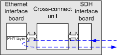
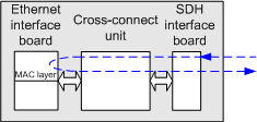
F-Ethernet Board Loopback: Through ETH Board we are Classified In-loop on ETH port into

1-      In-loop PHY Port Layer Loopback: the loop checks whether the MAC layer, SDH layer, and signals of the Ethernet board are normal where the Ethernet service that is transmitted from the NE is looped from the physical layer of the Ethernet port to the SDH layer


17


2-      In-loop MAC Port Layer Loopback: this loop checks whether the SDH layer and signals of the Ethernet board are normal where the Ethernet service that is transmitted from the NE is looped from the MAC layer of the Ethernet port to the SDH layer


18


Finally, I hope that my technical post helps everyone to know how to make Loopback on mentioned Boards to test Optical interface, Electric interface, Connectors, Cables, Modules and Cross-Connection.